
Image domain pansharpening method and system for spectral CT with large pixel energy discriminating detectors

a detector and large pixel energy technology, applied in image enhancement, instruments, image generation, etc., can solve the problems of poor performance of photon-counting detectors such as cdte/cdznte sensors, limited photon-counting detectors, and increased inter-pixel interferen

Active Publication Date: 2015-02-12
UNIVERSITY OF CHICAGO +2
View PDF8 Cites 5 Cited by
  • Summary
  • Abstract
  • Description
  • Claims
  • Application Information

AI Technical Summary

Benefits of technology

The patent text describes a method for improving the quality of computed tomography (CT) images using photon-counting detectors. These detectors have certain advantages, such as better image quality and reduced dose, but they also have disadvantages, such as high cost and limited performance at high flux rates. To address these issues, a dual-tube CT system has been proposed, which uses a combination of photon-counting detectors and conventional detectors. However, this method has not yet been widely used in clinical CT systems due to the high cost and limited sampling rate of photon-counting detectors. The patent text proposes a method to improve CT imaging using photon-counting detectors without suffering from their disadvantages. The technical effects of this patent text include improved image quality, reduced dose, and improved pansharpening of spectral images.

Problems solved by technology

The photon-counting detectors are generally limited by the high costs and their count-rate.
Furthermore, although the signal-to-noise ratio (SNR) in the photon-counting detectors is reduced at low flux levels for a small pixel size, the photon-counting detectors experience an increased level of inter-pixel interference due to the small pixel size.
On the other hand, the photon-counting detectors such as CdTe / CdZnTe sensors have poor performance at high flux levels, and consequently the SNR deteriorates.

Method used


Image

  • Image domain pansharpening method and system for spectral CT with large pixel energy discriminating detectors
  • Image domain pansharpening method and system for spectral CT with large pixel energy discriminating detectors
  • Image domain pansharpening method and system for spectral CT with large pixel energy discriminating detectors

Examples


Embodiment Construction

)

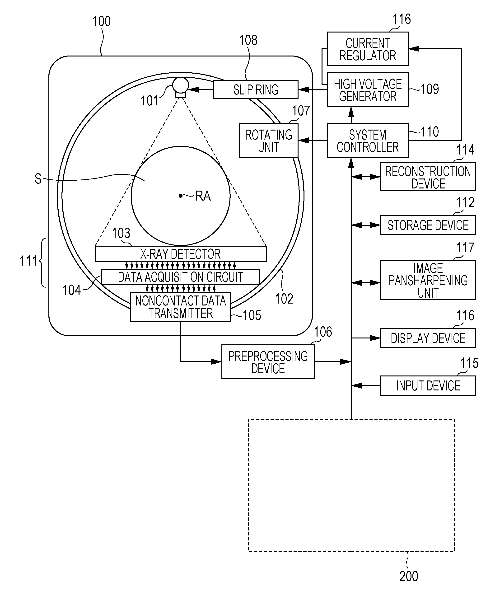
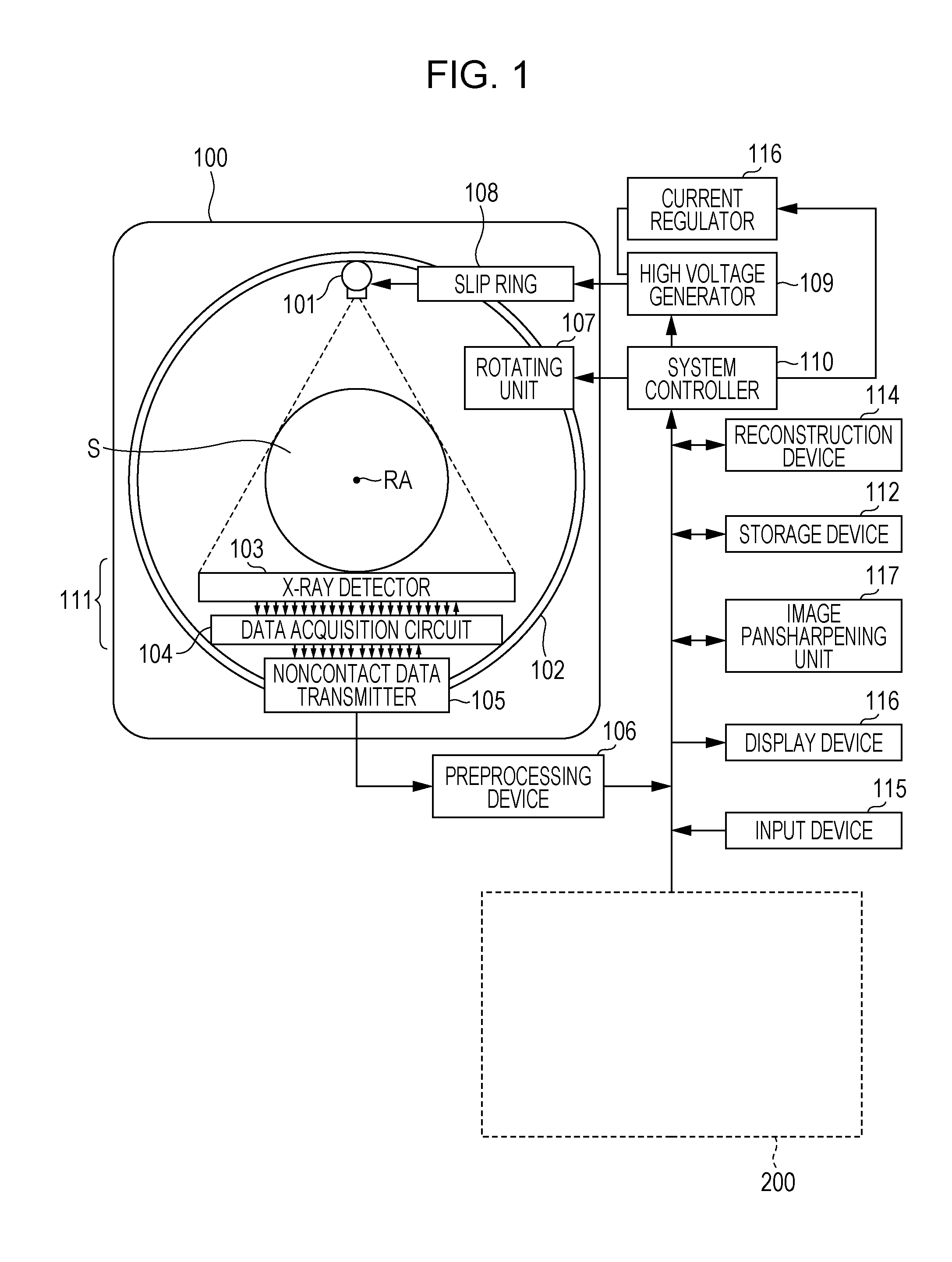
[0020]Referring now to the drawings, wherein like reference numerals designate corresponding structures throughout the views, and referring in particular to FIG. 1, a diagram illustrates one embodiment of the multi-slice X-ray CT apparatus or scanner for pansharpening a low-resolution spectral image according to the current invention including a gantry 100 and other devices or units. The gantry 100 is illustrated from a front view and further includes an X-ray tube 101, an annular frame 102 and a multi-row or two-dimensional array type X-ray detector 103. The X-ray tube 101 and X-ray detector 103 are diametrically mounted across a subject S on the annular frame 102, which rotates around axis RA. Although a single pair of the X-ray tube 101 and X-ray detector 103 is illustrated in the diagram, the embodiment for pansharpening a low-resolution spectral image optionally includes more than a single pair of the X-ray tube 101 and X-ray detector 103. A rotating unit 107 rotates the frame...


PUM


Abstract

A hybrid CT dataset is obtained from a combination of a integrating detector and a photon-counting detector. The hybrid CT dataset contains low-resolution photon-counting data and high-resolution integrating data. High-resolution panchromatic images are generated from the high-resolution integrating data, and low-resolution spectral images are generated from the low-resolution photon-counting data. The high-resolution panchromatic images inherit the resolution properties of the integrating detector while the low-resolution spectral images inherit the spectral information of the photon-counting detector. Subsequently, the low resolution spectral images are pansharpened based upon at least one high resolution panchromatic image that lacks spectral information according to a pansharpening algorithm.

Description

FIELD OF THE INVENTION[0001]The current invention is generally related to computer tomography (CT) image processing, and more particularly related to pansharpening of CT low-resolution spectral images using a high-resolution panchromatic (non-spectral) image.BACKGROUND OF THE INVENTION[0002]There is great desire to incorporate photon-counting detectors also known as energy discriminating X-ray detectors in computed tomography (CT). The photon-counting detectors have some potential to improve image quality, reduce dose and enable new clinical applications of CT. The photon-counting detectors acquire data including extra spectral information for providing material classification, improving quantitative imaging and reducing beam-hardening artifacts.[0003]Despite the above advantages over widely used energy-integrating detectors, the photon-counting detectors have certain disadvantages. The photon-counting detectors are generally limited by the high costs and their count-rate. Furthermo...

Claims


Application Information

Patent Timeline
Patent Type & Authority Applications(United States)
IPC IPC(8): G06T11/00G06T5/00G06T7/00
CPCG06T11/008G06T7/0012G06T11/003G06T2207/20208G06T2207/10081G06T2207/20172G06T2207/30004G06T5/003G06T3/4061G06T5/50G06T2207/10108G06T2210/41G06T5/73A61B6/4241
Inventor RIGIE, DAVIDLA RIVIERE, PATRICKPETSCHKE, ADAM
Owner UNIVERSITY OF CHICAGO
Learn More