
Vehicle heater

a heater and vehicle technology, applied in the field of vehicle heaters, can solve the problems of affecting the heating performance of the initial indoor heating, the thickness (air flow direction) of the heater, and the heater will be overheated, so as to improve the heat exchange performance, facilitate manufacturing, and improve the effect of heating performan

Active Publication Date: 2015-02-12
HANON SYST
View PDF12 Cites 10 Cited by
  • Summary
  • Abstract
  • Description
  • Claims
  • Application Information

AI Technical Summary

Benefits of technology

The present invention is a vehicle heater that is easy to make and small in size due to its thin heat generating part. It also improves heating performance by improving heat exchange. The heater is designed to simplify manufacturability and facilitate design changes. The second support part increases heat generation and structural stability. The heater includes hollow parts that allow air to turbulently flow, improving heat exchange performance. It also has louver fins to maximize heat exchange performance. The heater is formed using a carbon nano tube, which makes it easy to manufacture, control, and prevents overheating, improving safety.

Problems solved by technology

Therefore, in the winter, in a vehicle including the diesel engine, the heating of the heat exchange medium after the initial start-up becomes late, such that initial indoor heating performance is deteriorated.
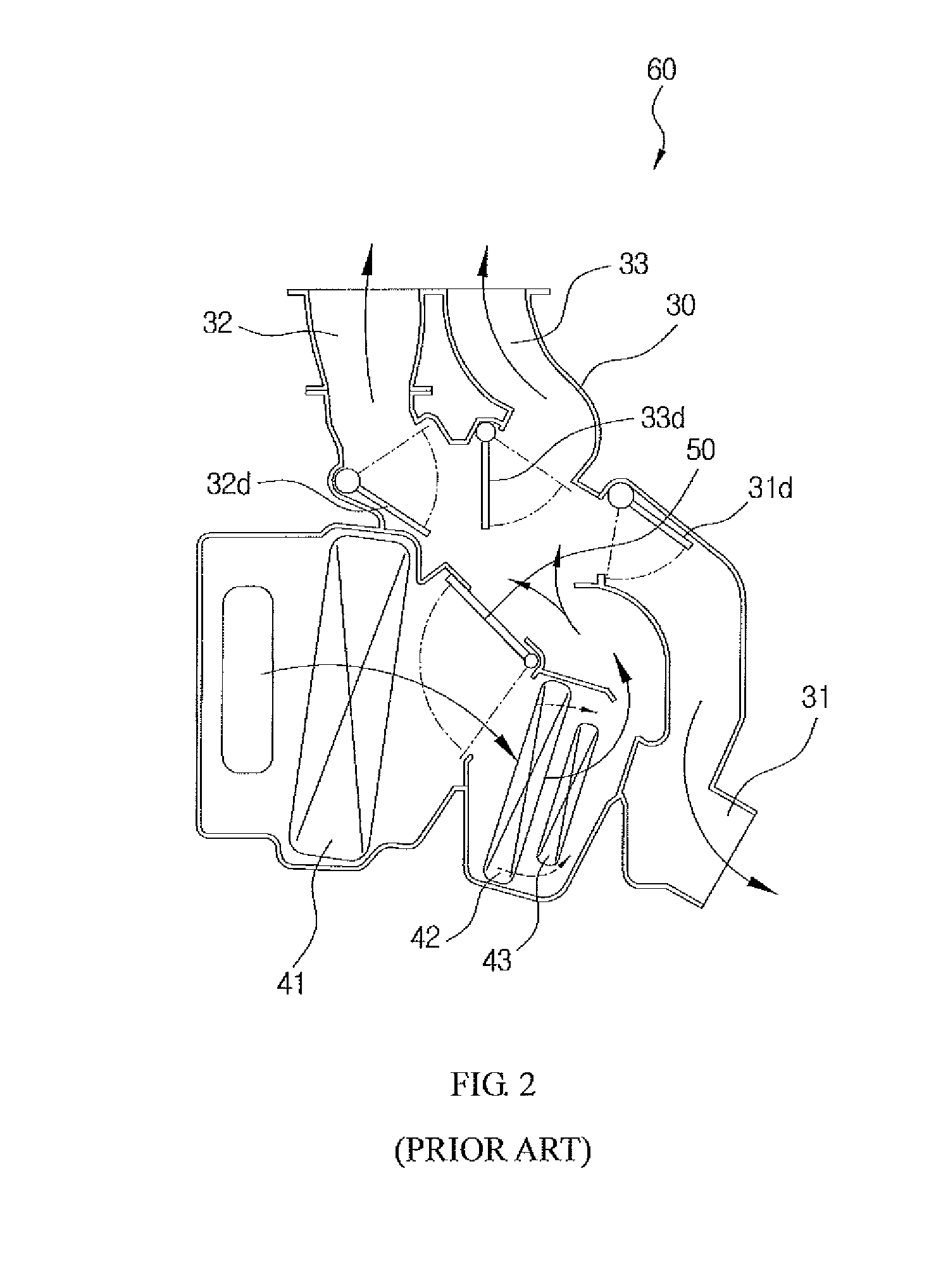
However, a space corresponding to a size of the air heating type heater is occupied in a situation in which it is difficult to secure a sufficient space in the engine room in accordance with the trend toward miniaturization and efficiency improvement, thereby making it possible to hinder the miniaturization.
Particularly, in the case of a cartridge heater using a nichrome wire, it is difficult to control a temperature, there is a risk that the cartridge heater will be overheated when the air is not blown toward the cartridge heater, an insulation problem due to a high voltage may occur, and there is a risk of a fire.
Therefore, there is a limitation in decreasing a thickness (air flow direction) of the PTC heater.
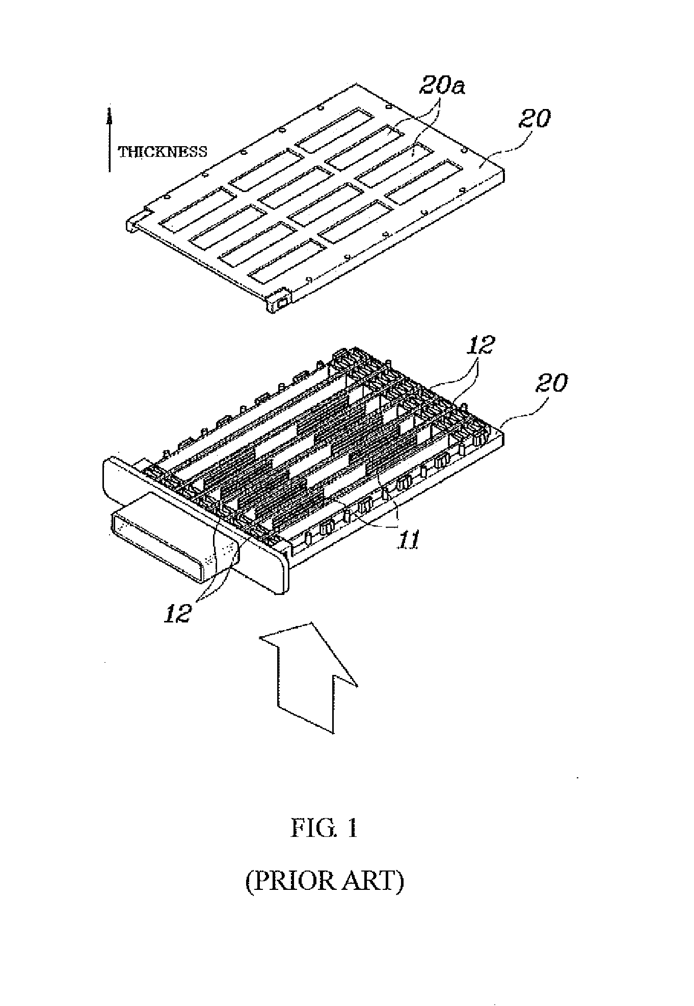
Particularly, in the PTC heater, since an electrical problem may occur in the case in which a heat radiating condition is not good, the heat radiating parts (generally, heat radiating fins) should be formed.
Therefore, a process of manufacturing and assembling the heat radiating parts is complicated, and entire durability of the PTC heater may be deteriorated in the case in which heat radiation is not effectively performed.
Therefore, air passing through upper and lower regions in which the PTC heater is not positioned is moved in a state in which it is not appropriately heated, such that heating performance cannot but be deteriorated.

Method used


Image

  • Vehicle heater
  • Vehicle heater
  • Vehicle heater

Examples


Embodiment Construction

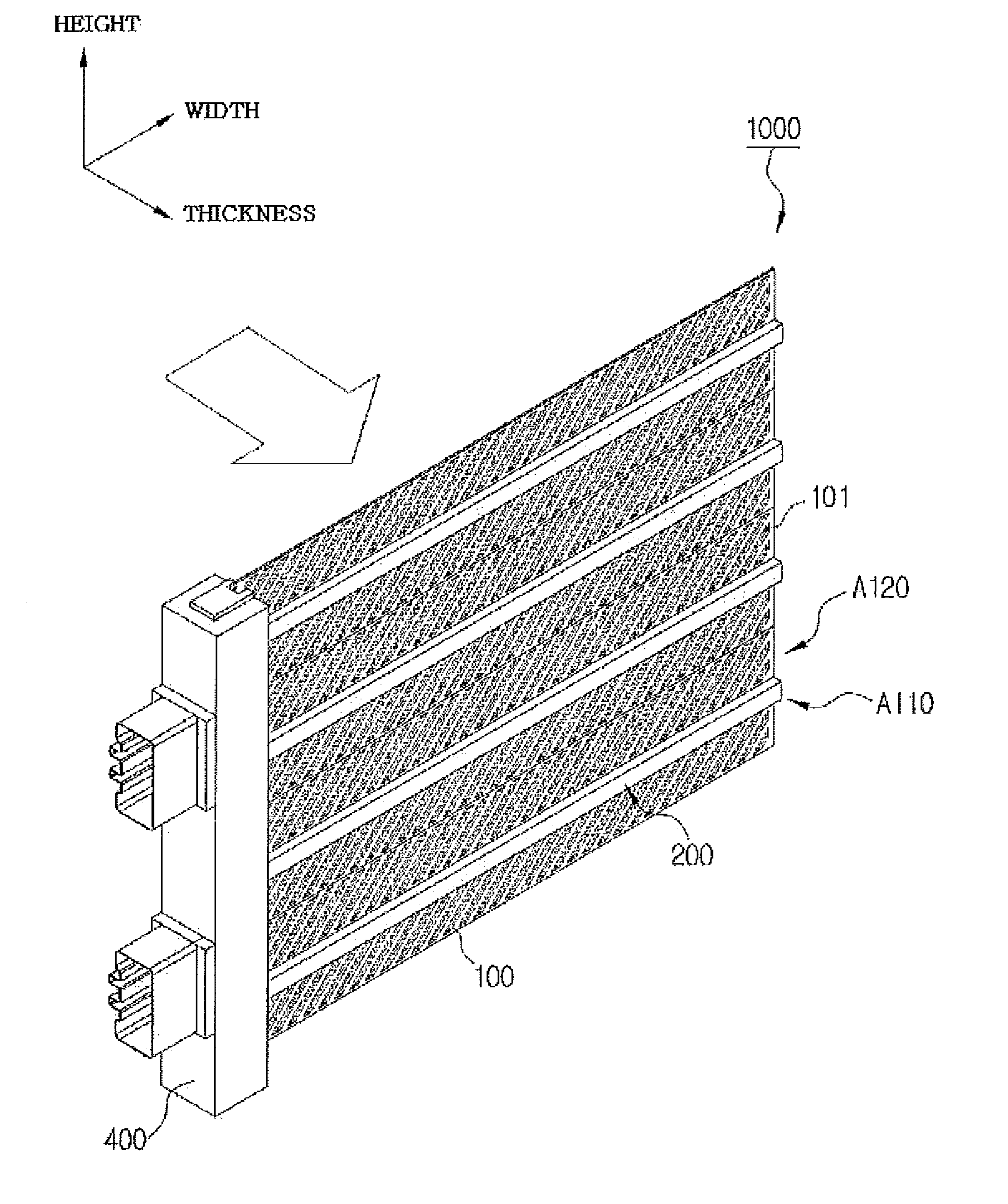
[0101]Hereinafter, a vehicle heater 1000 according to the present invention having the above-mentioned characteristics will be described in more detail with reference to the accompanying drawings.

[0102]The vehicle heater 1000 according to the present invention, which is a means heat-exchanged with a flowing fluid (air) to heat the fluid, is configured to include a first support part 100, a heat generating part 200, and a housing 400.

[0103]The first support part 100 has a plate form, is positioned perpendicularly to an air flow direction, and includes a first heat generation region A110 and a first air flowing region A120.

[0104]In the present invention, the air flow direction is denoted by an arrow in FIG. 3 and is defined as the same meaning as a thickness direction.

[0105]That is, a predetermined region of the first support part 100 forms the first heat generation region A110 corresponding to a region in which the heat generating part 200 is positioned, and the remaining region form...


PUM


Abstract

Provided is a vehicle heater that is capable of being easily manufactured and being miniaturized due to a decrease in a thickness by forming a heat generating part using a first support part (and a second support part) positioned perpendicularly to an air flow direction and having a plate form and is capable of improving heating performance by improving heat exchange performance.

Description

FIELD OF THE INVENTION[0001]The present invention relates to a vehicle heater, and more particularly, to a vehicle heater that is capable of being easily manufactured and being miniaturized due to a decrease in a thickness by forming a heat generating part using a first support part (and a second support part) positioned perpendicularly to an air flow direction and having a plate form and is capable of improving heating performance by improving heat exchange performance.BACKGROUND OF THE INVENTION[0002]As a heating means, which is used in order to raise an external temperature, means using various methods have been suggested. In addition, the heating means has been used for various purposes.[0003]Particularly, a heating means that is in charge of indoor heating among heating means included in an engine room of a vehicle is configured so that a heat exchange medium for lowering a temperature of an engine heats external air while being circulated in a heater core, thereby heating an i...

Claims


Application Information

Patent Timeline
Patent Type & Authority Applications(United States)
IPC IPC(8): B60H1/22
CPCB60H1/2225F24H3/0429F24H3/0435F24H3/062F24H2250/04H05B3/20H05B3/30H05B3/44H05B2203/023
Inventor GU, JUNG SAMOH, KWANG HUNJEON, YOUNG-HASONG, JUN YOUNGLIM, HONG-YOUNG
Owner HANON SYST
Learn More