Intravascular blood pump

Active Publication Date: 2015-02-19
ABIOMED EURO
View PDF1 Cites 66 Cited by
  • Summary
  • Abstract
  • Description
  • Claims
  • Application Information

AI Technical Summary

Problems solved by technology

Further increase of the rotational speed is difficult because of blood damage.
A severe problem with foldable axial blood pumps is the required dimensional accuracy.
These requirements are difficult to fulfil with foldable blood pumps because of the flexibility of the foldable housing.
More specifically, during use and in particular due to the bends in the vessel course, there is always the danger that the housing does not perfectly assume the predefined shape.
Instead, unexpected forces acting locally on the flexible housing may cause the impeller to contact

Method used


Image

  • Intravascular blood pump
  • Intravascular blood pump
  • Intravascular blood pump

Examples


second embodiment

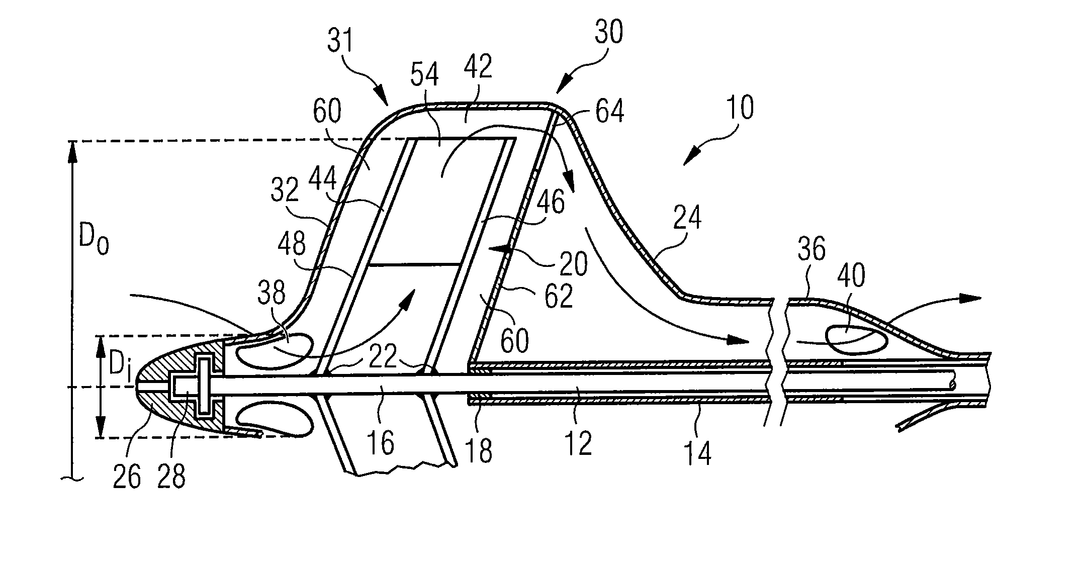
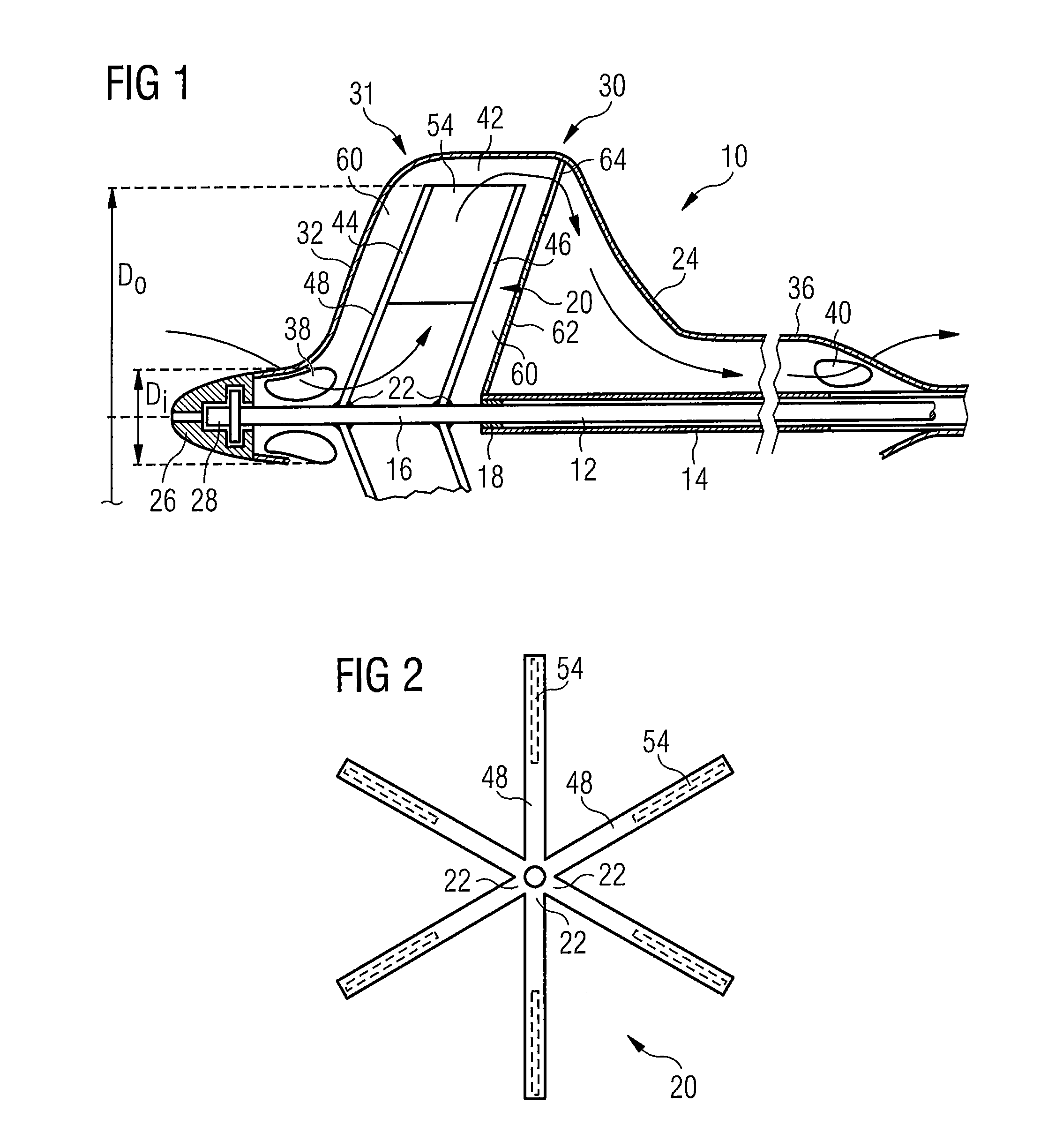
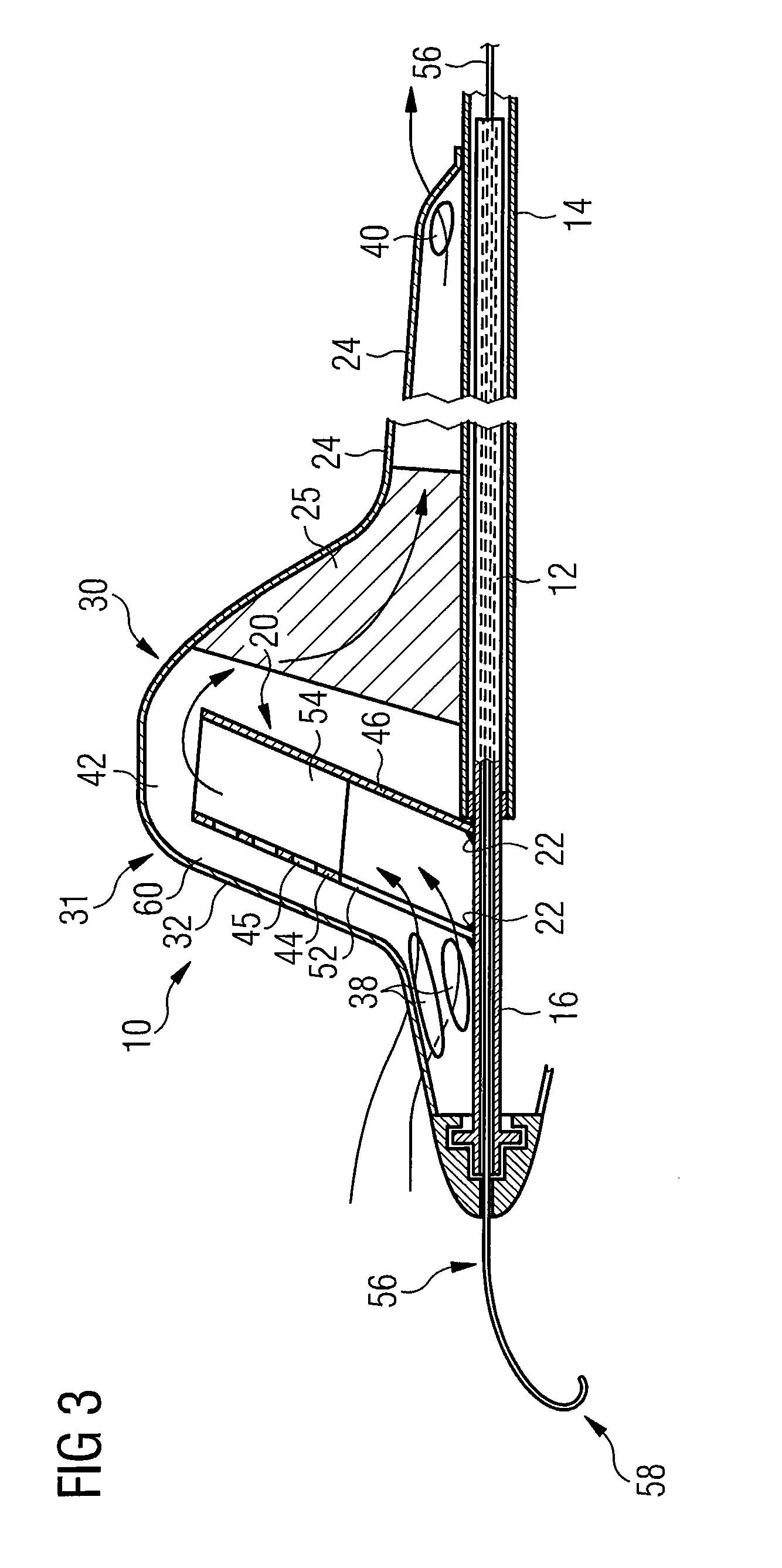
[0038]the blood pump is shown in FIG. 3. A guide wire 56 extends through the shaft 12, the end 58 of said guide wire being “J-” shaped and possibly “pigtail”-shaped, wherein the blood pump 10 can be inserted into the heart via said guide wire 56. Before operation, the guide wire 56 is removed. Such guide wire 56 may likewise be used in the other embodiments described herein.

[0039]The second embodiment shown in FIG. 3 further differs from the first embodiment shown in FIG. 1 by the structure of the impeller 20, more particularly by its front and rear supporting structures 44, 46. Firstly, the rear supporting structure 46 is formed as a plate which may be formed by the six spokes 48 interconnected by a polymer skin to define a back plate which replaces the partition or rear wall 62 of the first embodiment shown in FIG. 1.

[0040]Secondly, the front supporting structure 44 is also formed as a plate, e.g. with a polymer skin mounted between the spokes 48. However, the front supporting str...

fourth embodiment

[0045]A second difference in the fourth embodiment shown in FIG. 5 as compared to the previously described embodiments is that the impeller 20 has an outer diameter increasing from the inflow end towards the outflow end. This structure supports blood flow in the desired direction, here from distal to proximal, and offers a maximized discharge diameter, thereby increasing the delivery rate.

fifth embodiment

[0046]A fifth embodiment is shown in FIG. 6. It differs from the previous embodiments mainly by the impeller 20 being positioned further away from the blood flow inlet openings 38. This arrangement provides the advantage that blood flowing through the inlet openings 38 will have no swirl when entering axially, the swirl of the blood being created inside the housing 24. When the impeller 20 is arranged closer to the blood flow inlet openings 38, as in the previous embodiments, the swirl imposed on the blood by the impeller 20 will be partly imparted through the inlet openings 38 onto the blood outside the housing 24, due to the high viscosity of the blood. This causes energy losses. The arrangement further away from the inlet openings 38, as shown in FIG. 6, avoids such energy losses.

[0047]FIGS. 7 to 9 show different methods of placing the blood pump in the heart. FIG. 7 shows the blood pump 10 according to the first and second embodiments of FIGS. 1 to 3. The blood pump 10 is arrang...


PUM


Abstract

A foldable, intravascularly insertable blood pump (10) comprises a foldable, radially delivering impeller (20) accommodated in a foldable housing or envelope (24). Axially before and behind the impeller a clearance (60) is provided between the impeller (20) and the front and back walls (32, 62) of the housing (24), the clearance being at least 0.2 mm. Preferably, the space defined between adjacent blades (54) of the impeller (20) is open towards the front wall (32) of the housing (24).

Description

FIELD OF THE INVENTION[0001]The present invention relates to an intravascularly insertable blood pump comprising a housing in which a radially delivering impeller is arranged for rotation and further comprising a catheter accommodating a flexible shaft connected to an external motor for driving the impeller. More particularly, the present invention relates to an expandable intravascular blood pump.BACKGROUND OF THE INVENTION[0002]Rotary blood pumps are known which are inserted into the heart for supporting the pumping capacity of the natural heart. Insertion is performed intravascularly, namely through the blood vessel system of the patient. It is thus important that, upon insertion, the maximum diameter of the blood pump is small, preferably not exceeding 4 mm (12 French). Further, the blood pump should be flexible for the purpose of conforming to the bends of the vessel course.[0003]The aforementioned rotary blood pumps that are currently in use are axially delivering blood pumps,...

Claims


Application Information

Patent Timeline
IPC IPC(8): A61M1/10A61M1/12
CPCA61M1/125A61M1/1024A61M60/414A61M60/148A61M60/808A61M60/865A61M60/81A61M60/812A61M60/13A61M60/818A61M60/226A61M60/122A61M25/01Y10S415/90A61M60/855
Inventor SIESS, THORSTENABOULHOSN, WALID
Owner ABIOMED EURO
Why Eureka
Try Eureka