
Monoblock Engine

a monoblock engine and crankcase technology, applied in the direction of machines/engines, mechanical equipment, cylinders, etc., can solve the problems of increased manufacturing time, assembly time and development & production costs, increased cost, and further cost increase, so as to simplify the design of cylinders and manifolds, reduce production costs, and reduce leakage at the interface of monoblocks and crankcases.

Inactive Publication Date: 2015-02-26
MAHINDRA & MAHINDRA LTD
View PDF7 Cites 6 Cited by
  • Summary
  • Abstract
  • Description
  • Claims
  • Application Information

AI Technical Summary

Benefits of technology

The present invention is a monoblock engine that integrates the cylinder head and block, eliminating critical joints and reducing the need for gaskets and mechanical fasteners. The engine incorporates water coolant jackets, intake and exhaust manifolds, and vertical valves. A push-fit cylinder liner is secured in place to eliminate fuel leakage. The water coolant jackets for the head and block are connected using four water jacket gateways or connectors. The monoblock engine is easy to install and has optimized performance for both single and multi-cylinder engines. Its unique design also enables better performance and more efficient cooling.

Problems solved by technology

Today's engine designs are extremely complex and the number of components have been increasing over the past couple of decades leading to increased manufacturing time, assembly time and development & production costs.
The faces on which these joints are interfaced require extremely accurate and precise machining, leading to further cost increase.
Any drop in quality control in these crucial operations also leads to below-par quality / performance and part rejection.
The compression in the cylinder potentially causes a leak to form in the gasket.
If the faulty gasket is not replaced and if it fails, a variety of problems can occur, ranging from compression loss (leading to power reduction, or a rough engine), to exhaust gases being forced into the cooling system, leading to the engine overheating and increased engine wear due to the oil being mixed with antifreeze.
Coolant can leak into the cylinders, causing the exhaust to issue steam.
If a very large amount of coolant leaks, the so-called hydro locks can occur, causing extensive engine damage.
It thus adds up the assembly time and consequently the manufacturing cost.
In conventional design of the casting process, the draw distance is significantly high and leads to improper disengagement of the cast engine parts.
It is often found that the cast parts need repairing after casting.
Presence of undercuts also increases the number of elements in the mould, and also the cost of a core for producing a particular feature involving an undercut is significantly higher than an ordinary mould of equal volume.
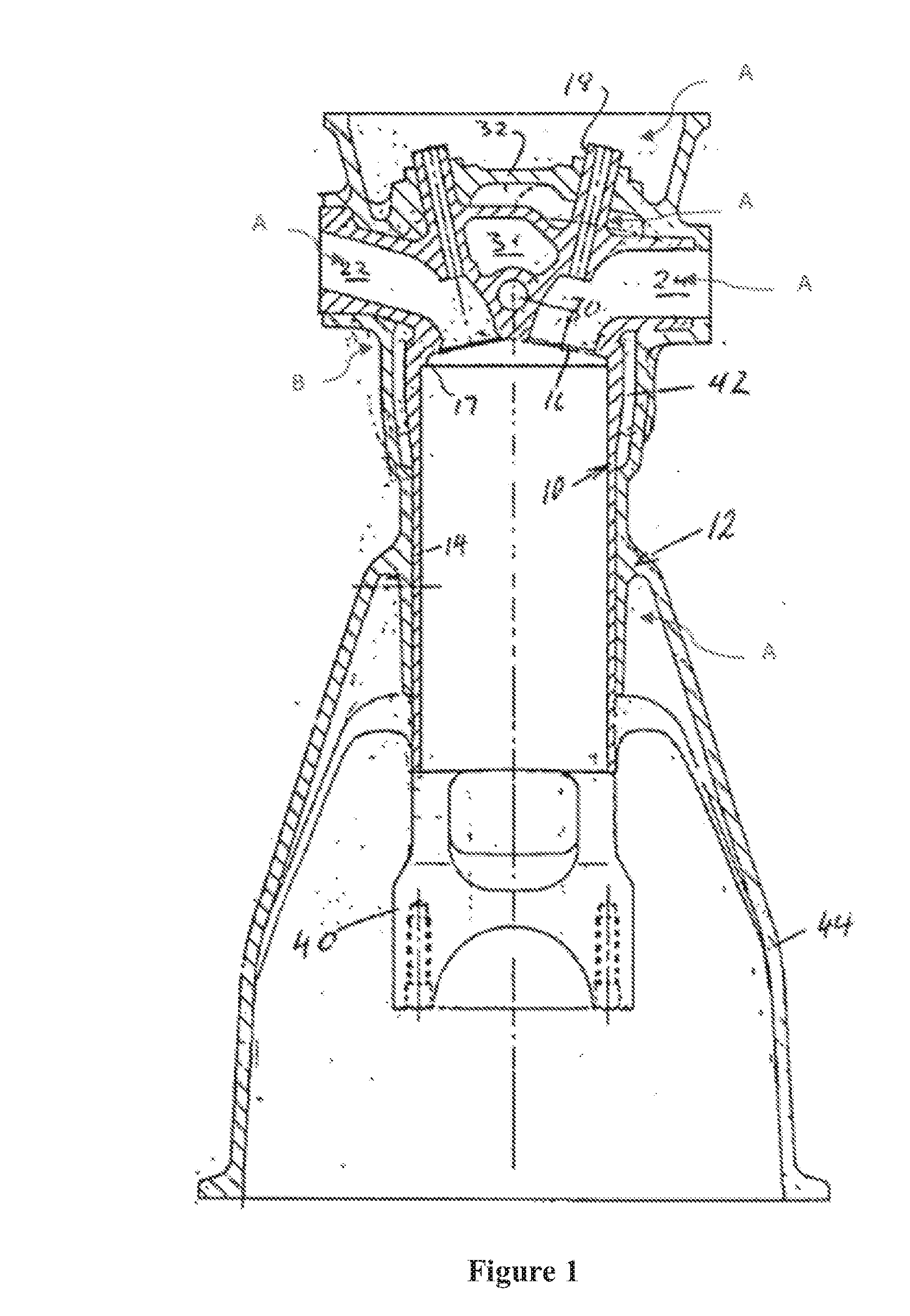
Undercuts (part indicated as ‘B’ in FIG. 1) lead to higher costs in terms of special materials, additional tooling and lower productivity.
A further problem with the convention monoblock engines is to do with the honing of cylinder bores.
In conventional mono blocks—since the mono-block engines are bigger and complex in structure due to integration of cylinder head and manifolds—it was very difficult to hone them using traditional honing processes.
A further drawback of the conventional monoblock engines is that fixing the monoblock assembly to the crankcase is not easy.
Long studs are liable to breakage under critical loads.
The presence of pillars not only adds to the material and construction costs but it also makes the water jacket design more complex.
The conventional monoblock engines are found to be cumbersome to cast and manufacture, have ill-efficient water jackets.

Method used


Image

  • Monoblock Engine
  • Monoblock Engine
  • Monoblock Engine

Examples


Embodiment Construction

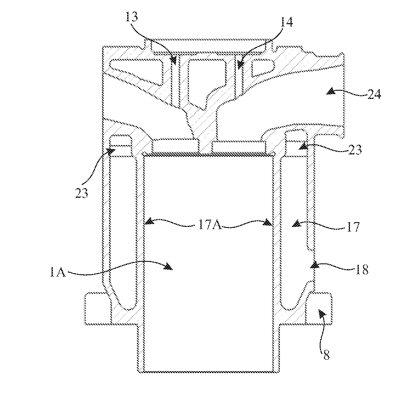
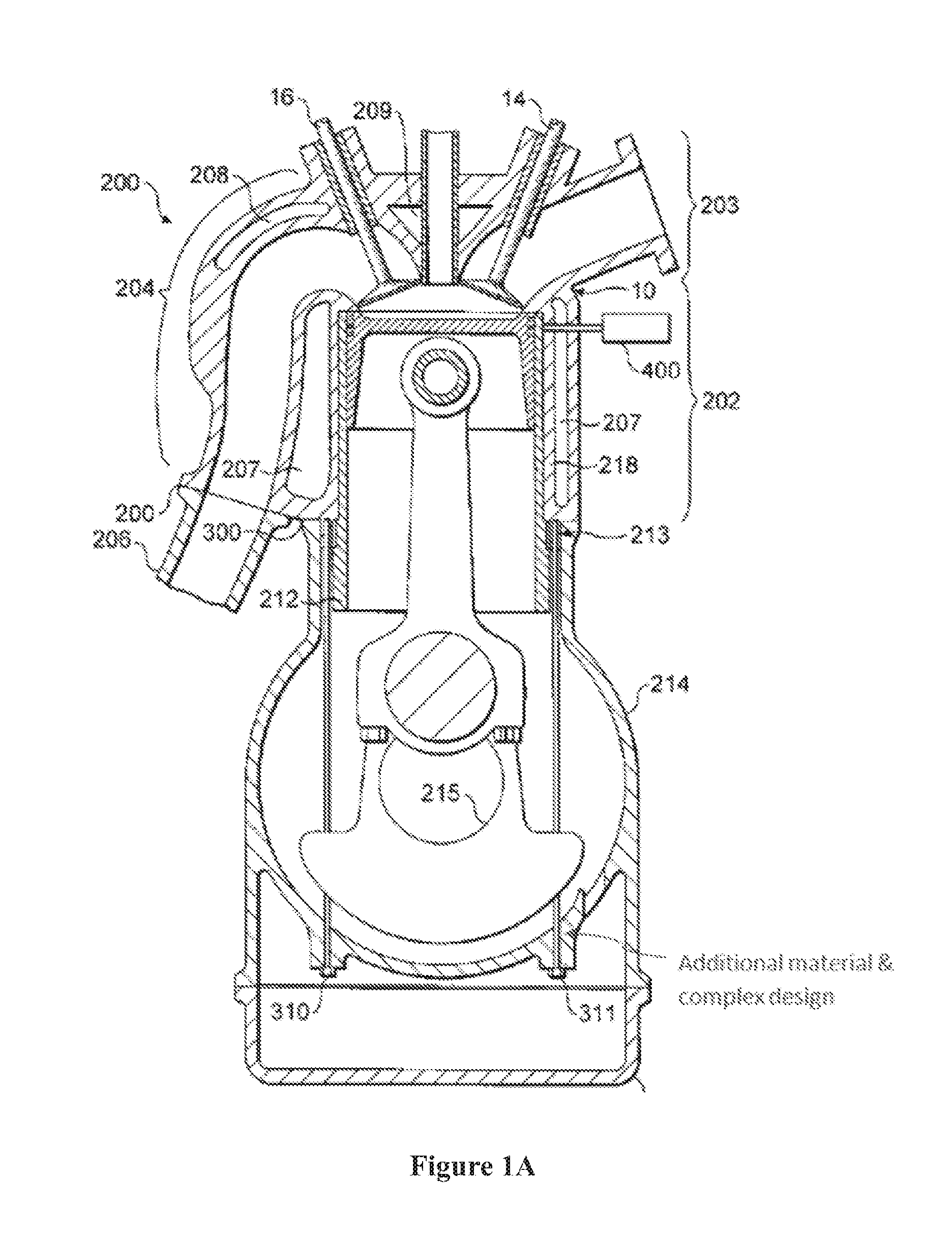
[0031]As shown in FIGS. 1 and 1A and FIGS. 2 and 3, the external and internal construction of the monoblock engine (1) are such that there are no parts that protrude awkwardly which when cast would come in the way of extracting from the casting mould.

[0032]Accordingly, the cylinder head (2) and manifold (at least one) are integrated with cylinder block (3) and shaped as a monoblock. By integrating cylinder head (2) and manifolds with block (3), the critical joint between head (2) and the block (3), and head (2) and the intake manifold (5) will be eliminated. At the same time, gaskets and mechanical fasteners for tightening also can be eliminated. The water jacket (17) design is communized and optimized for both head (2) and the block (3) for better performance. Furthermore, all openings are maintained on a partition line (19) so that core design will be easier. Special core removal holes (18) are provided in order that the water jacket (17) may be constructed as a single continuum a...


PUM

PropertyMeasurementUnit
Timeaaaaaaaaaa
Thicknessaaaaaaaaaa

Abstract

The present invention discloses a monoblock engine in which the head and the block of the engine are cast integrally. The engine incorporates a cylinder and water coolant jackets, intake manifold and an exhaust manifold, vertical intake and exhaust valves, core removal holes, and a push-fit type cylinder liner which is secured in place so that leakage of fuel from the cylinder is eliminated. The water coolant jackets for the head and the block are connected using four water jacket gateways or connectors. The monoblock is fitted with the crankcase using a leak proof & robust flange-joint and mechanical fastening system which is easy to install. The invention is embodied for a single cylinder engine as well as multi-cylinder engines. By integrating cylinder head and manifolds with block, the critical joint between head and block and head and intake Manifold will be eliminated. At the same time, gasket and mechanical fasteners for tightening also can be eliminated. The water jacket design is communized & optimized for both head and block for better performance.

Description

FIELD OF INVENTION[0001]The invention relates to an engine for automotive vehicles. In particular the invention relates to engines in which the cylinder head and block are cast integrally and which has leak proof joints and which is easy to cast and attach to the crankcase.BACKGROUND OF INVENTION[0002]Monoblock engines have been known. Currently, the conventional architecture of a four-stroke poppet valve internal combustion engine is a combination of an integrated crankcase and cylinder block (formed as one unit) and a separately formed cylinder head, the cylinder head being bolted to the top of the cylinder block with a high pressure cylinder head gasket sealing the junction between the cylinder head and the cylinder block. A separately formed exhaust manifold is bolted to the cylinder head, to collect combusted gases expelled from the cylinders and to relay them to e.g. a turbocharger turbine or directly to an exhaust system (exhaust pipe and catalyst combination).[0003]Internal ...

Claims


Application Information

Patent Timeline
IPC IPC(8): F02F1/00B22D25/02F02F1/04F02F1/10F02F1/06
CPCF02F1/002F02F1/102B22D25/02F02F1/004F02F1/045F02F1/06
Inventor GANLA, ABHAYKUMAR NARAYANRAOSATDIVE, SACHIN PRABHAKARSESHATHRI, DHATCHNAMOORTHY
Owner MAHINDRA & MAHINDRA LTD
Learn More