Slide scanner with dynamic focus and specimen tilt and method of operation

a scanning machine and dynamic focus technology, applied in the field of microscopic imaging of large specimens, can solve the problems of increased signal/noise and amplitude, increased tiling artifact chances, and inability to achieve proper focus across the whole width of the strip, so as to prevent the effect of tiling mismatch at the edges

Active Publication Date: 2015-02-26
HURON TECH INT
View PDF9 Cites 42 Cited by
  • Summary
  • Abstract
  • Description
  • Claims
  • Application Information

AI Technical Summary

Benefits of technology

[0029]8. It is an object of this invention to provide an instrument and method of scanning a large microscope specimen in which focus and tilt of adjacent scan strips are adjusted dynamically during scan such that the edges of adjacent strips are acquired at the same focus positions to prevent focus mismatch at the edges of adjacent strips.

Problems solved by technology

Such images may contain tiling artifacts caused by different focus positions for adjacent tiles.
For large specimens, thousands of tiles may be required to image the entire specimen, requiring many changes in focus which increase the chances of tiling artifacts.
When a CCD-based TDI array is used, each line image stored in memory is the result of integrating the charge generated in all of the previous lines of the array while the scan proceeds, and thus has both increased signal / noise and amplitude (due to increased exposure time) when compared to the result if a linear array detector were used.
If the specimen is not flat, or the specimen is tilted about the scan direction, proper focus may not be achieved across the whole width of the strip.
In addition, focus at the edge of adjacent strips may be different, making it difficult to stitch image strips together to assemble a complete image of the specimen without focus mismatch at the edge of strips.
These problems are made worse when magnification is increased (which decreases depth of field) and when the width of the scan strip on the specimen is increased.

Method used


Image

  • Slide scanner with dynamic focus and specimen tilt and method of operation
  • Slide scanner with dynamic focus and specimen tilt and method of operation
  • Slide scanner with dynamic focus and specimen tilt and method of operation

Examples


first embodiment

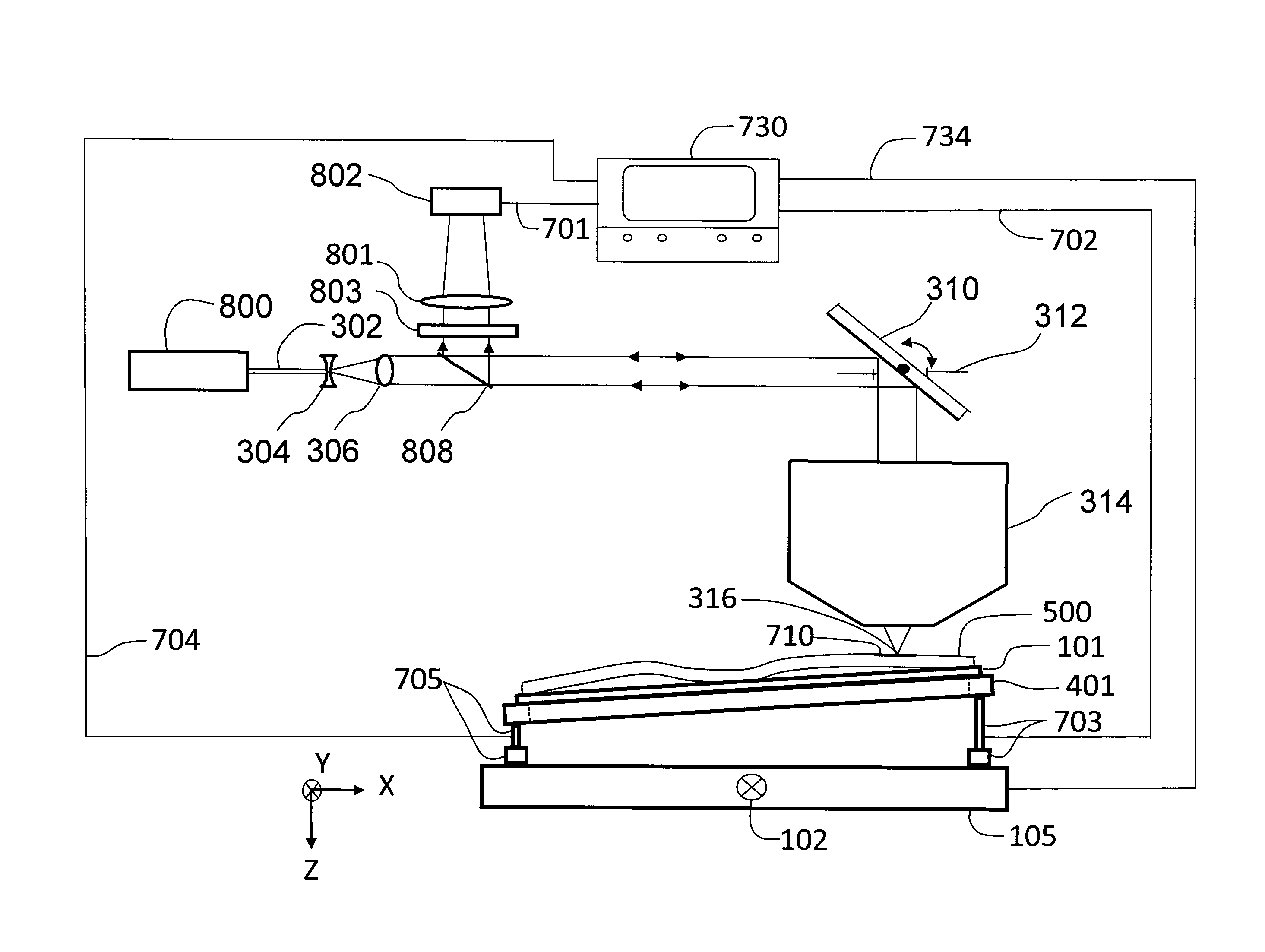
[0044]FIG. 4 shows a schematic representation of a brightfield scanner that performs simultaneous focus and specimen tilt adjustments during scanning that is this invention. A large tissue specimen 400 (or other specimen to be imaged) is mounted on microscope slide 101 which is held by slide mount 401. Slide mount 401 is supported on the left by hinge 420 (which rotates about the Y axis) and on the right by piezoelectric positioner 402, which moves in the Z direction. Slide mount 401 is open in the centre (like a picture frame) to allow the microscope slide to be illuminated from below by illumination source 110. Light passing through the specimen is collected by infinity-corrected microscope objective 115 which is focused on the specimen by piezo positioner 120, controlled by computer 430 through control cable 433. The computer 430 can be any central processing unit. The microscope objective 115 and tube lens 125 form a real image of the specimen on linear detector array 130. Data ...

third embodiment

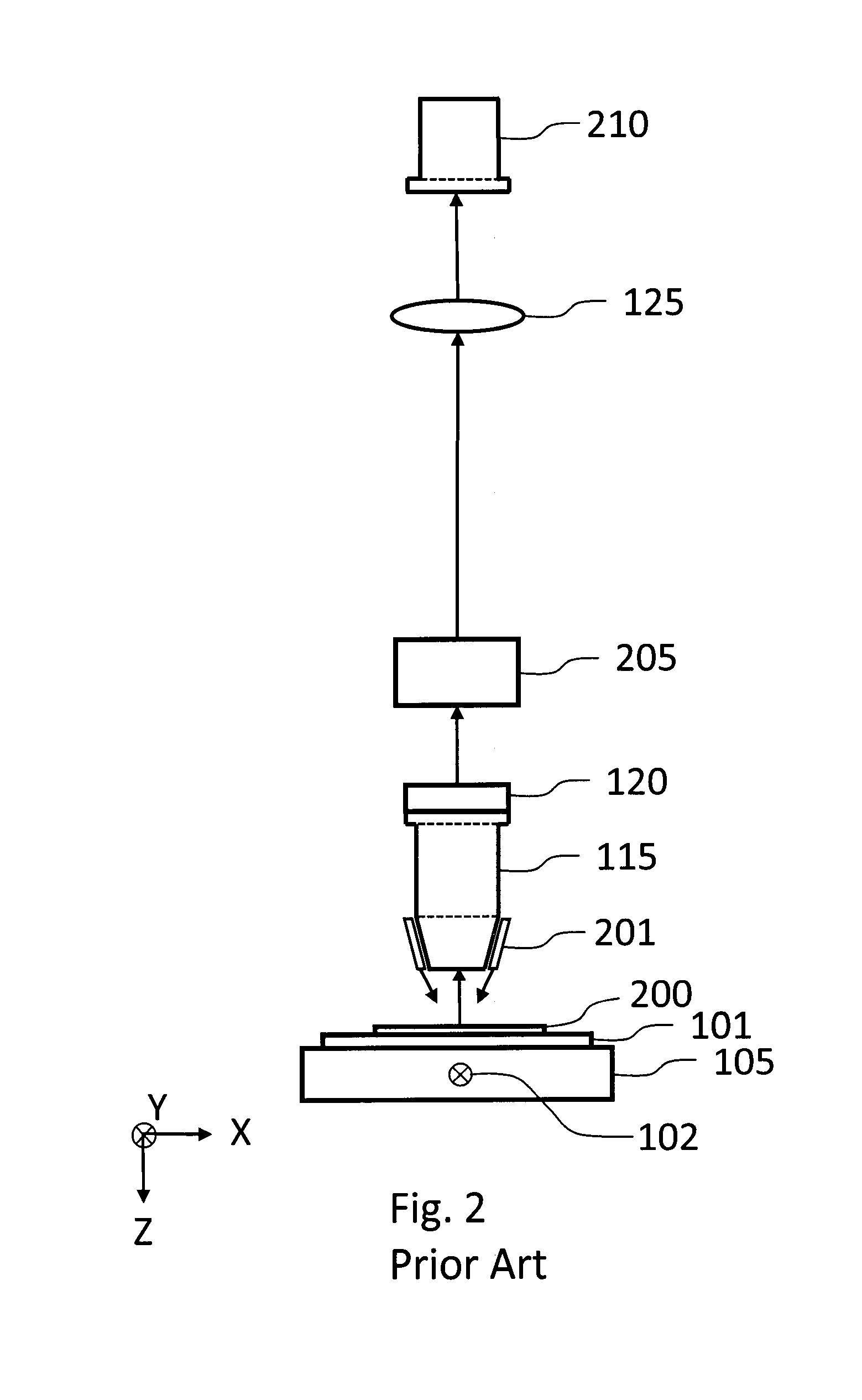
[0050]In FIG. 5, if TDI detector array 210 is replaced by an ordinary two-dimensional (2D) detector array (not a TDI array), then Moving Specimen Image Averaging can be used to acquire fluorescence image strips as described above. This is this invention. Both focus position and tilt can be measured by performing a Z-scan at several Y positions along each strip before scanning, with the specimen tilt set at zero.

[0051]With the detector parallel to the scan plane, a Z-scan is performed by moving the microscope objective in the Z direction using the piezo positioner to a series of equally-spaced positions in Z, while storing the resulting series of 2D images, each of which has the same width as the scan strip, using the 2D detector (or alternatively, a Z-scan can be performed by moving either the detector or the specimen in the Z direction). This results in a 3D image stack at each Y position, and if the detector used as an example in the description above is used, this image stack con...

fourth embodiment

[0058]Dynamic focus and dynamic tilt as described in this fourth embodiment will also be useful for second and third harmonic generation microscopy, and coherent anti-Stokes Raman scattering microscopy (CARS microscopy), in both scanning microscope and scanning macroscope configurations. Dynamic focus and dynamic tilt will also be useful in a scanning laser microscope used for two-photon or multi-photon fluorescence, and second and third harmonic generation microscopy.

[0059]When used for two-photon or multi-photon fluorescence, either a descanned detector where emission light is descanned by the scanning mirror (as shown in FIG. 8) or beam scanner (as shown in FIG. 9) or a non-descanned detector (where light is not descanned by the scanning mirror) can be used. In one arrangement, a non-descanned detector is placed below the microscope slide to receive fluorescence transmitted through the slide. A description of non-descanned detection is shown in “Multi-Photon Molecular Excitation ...


PUM


Abstract

An instrument and method for scanning large microscope specimen on a specimen holder has a scanning optical microscope that is configured to scan the specimen in one of brightfield and fluorescence. The specimen is dynamically tillable about a scan direction during a scan to maintain focus along the length of each scan line as the scan proceeds. A three dimensional image of the specimen can be obtained wherein the specimen tilt and relative focus are maintained from a first image contour to a second image contour through a thickness of a specimen.

Description

BACKGROUND OF THE INVENTION[0001]1. Field of the Invention[0002]This invention relates to the fields of microscopic imaging of large specimens with particular emphasis on brightfield and fluorescence imaging. Applications include imaging tissue specimens, genetic microarrays, protein arrays, tissue arrays, cells and cell populations, biochips, arrays of biomolecules, detection of nanoparticles, photoluminescence imaging of semiconductor materials and devices, and many others. More particularly, this invention relates to an instrument and method for scanning a large microscope specimen in brightfield or fluorescence with a scanning optical microscope and tilting the specimen about a scan direction during a scan to maintain focus along a length of each scan as the scan proceeds.[0003]2. Description of the Prior Art[0004]Several technologies are used for imaging large specimens at high resolution. Tiling microscopes record an image of a small area of the specimen using a digital camera...

Claims


Application Information

Patent Timeline
Patent Type & Authority Applications(United States)
IPC IPC(8): G02B21/36G02B21/26G02B21/00
CPCG02B21/365G02B21/26G02B21/006G02B21/0076G02B21/008G02B21/12G02B21/16
Inventor DIXON, ARTHUR EDWARDDAMASKINOS, SAVVAS
Owner HURON TECH INT
Why Eureka
Try Eureka