Supercharge Your Innovation With Domain-Expert AI Agents!

Stamper, method of manufacturing the same, and method of manufacturing molded body

a technology of molded body and manufacturing method, which is applied in the direction of manufacturing tools, cell components, instruments, etc., can solve the problems of poor product quality, small defect of molded body, and easy to be noticed, and achieves excellent appearance quality, good product quality, and easy manufacturing.

Inactive Publication Date: 2015-03-05
MITSUBISHI RAYON CO LTD
View PDF0 Cites 14 Cited by
  • Summary
  • Abstract
  • Description
  • Claims
  • Application Information

AI Technical Summary

Benefits of technology

The invention provides a method for manufacturing a stamper that can easily create molded bodies with antireflection, antiglare, and excellent appearance quality. The stamper is designed for good productivity, resulting in high-quality molded bodies. The method also includes steps for creating the molded body with these properties. The technical effects of the invention include improved optical properties, reduced glare, and improved appearance quality for molded bodies.

Problems solved by technology

However, a molded body which simply has a fine rugged structure on the surface has excellent antireflection properties but also has too high transmittance.
Hence, a few defects of the molded body such as cracks, scratch, or dirt of the surface of the molded body come to be noticeable in some cases.
In addition, when the molded body is attached to an object, defects of the object or moire from the object, which do not cause problems in the related art, come to be noticeable in some cases.

Method used


Image

  • Stamper, method of manufacturing the same, and method of manufacturing molded body
  • Stamper, method of manufacturing the same, and method of manufacturing molded body
  • Stamper, method of manufacturing the same, and method of manufacturing molded body

Examples


example 1

Manufacture of Stamper

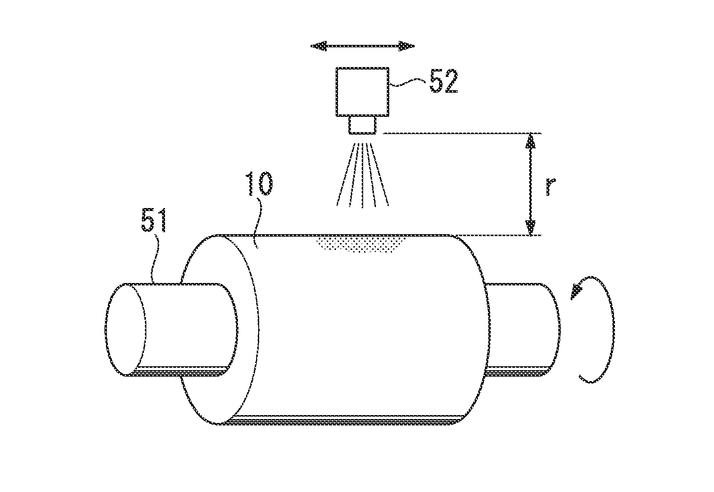
[0187]An aluminum rolled sheet (having a thickness of 0.5 mm and a Vickers hardness of 35 Hv) having a purity of 99.3 mass % was subjected to a blast process using glass beads (manufactured by Potters-Ballotini Co., Ltd., “J400”, a median particle size of 45 μm) as an abrasive having spherical shapes without sharp shapes (hereinafter, also referred to as “non-sharp spherical shapes”) under the conditions of a discharge pressure of 0.05 MPa, an operation pitch of 2.5 mm, a discharge nozzle movement speed of 20 m / min, and a distance (r) from the tip end of the discharge nozzle to the surface of an aluminum base material to be subjected to the blast process of 520 mm.

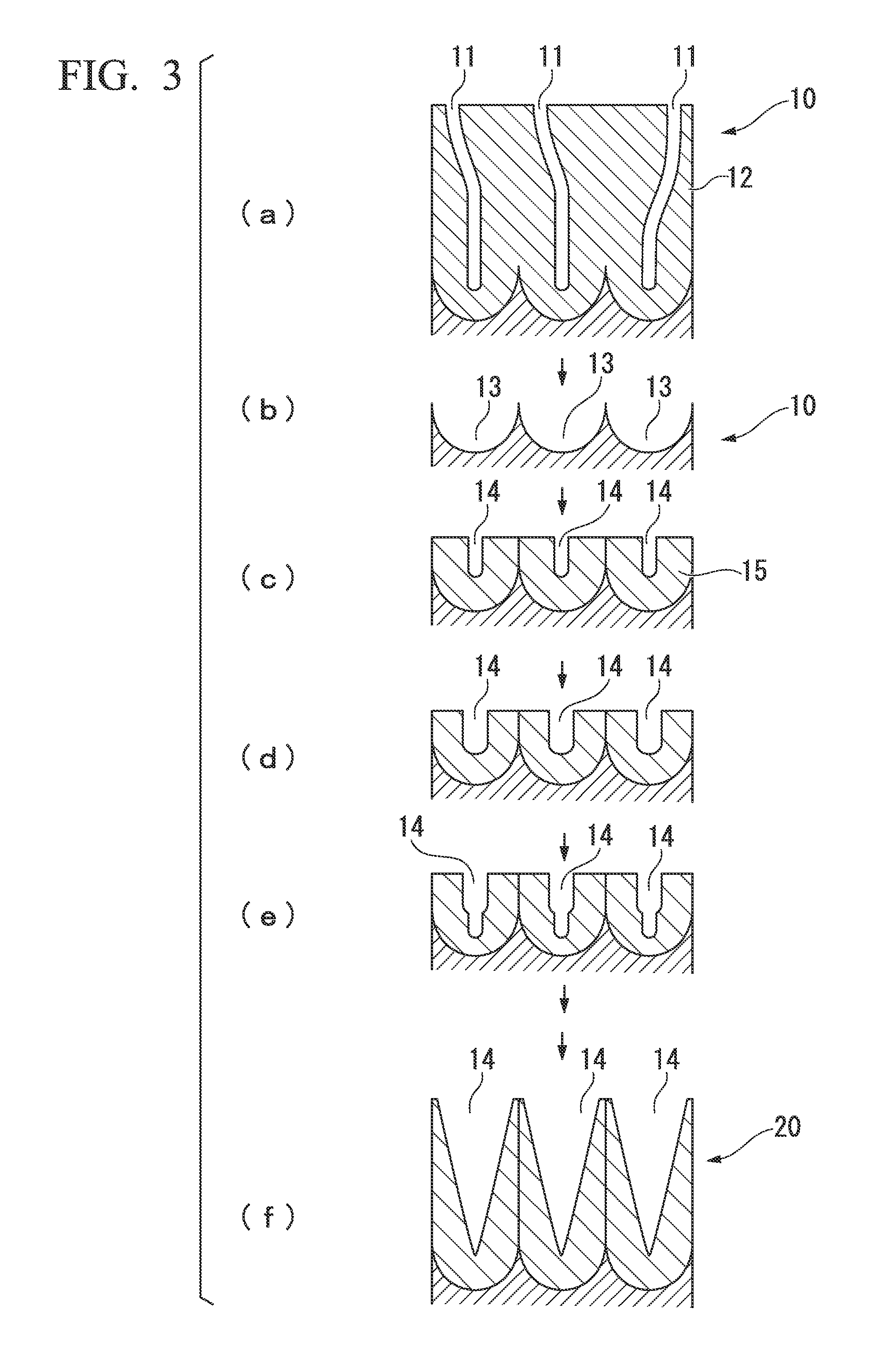
[0188]Subsequently, the aluminum base material subjected to the blast process was anodized in an aqueous solution of 0.3 M oxalic acid under the conditions of a bath temperature of 16° C. and a DC voltage of 40V for 30 minutes, thereby forming an oxide film (process (a)). The formed oxide film was tem...

example 2

[0200]An aluminum ingot having a purity of 99.97 mass % was cut into a roll shape having a diameter of 200 mm and a width of 320 mm, and the surface thereof was cut and mirror-finished so as to be used as an aluminum base material. A stamper was manufactured in the same manner as Example 1 except that blasting conditions were changed to those in Table 1. A molded body was manufactured in the same manner as Example 1 by using the obtained stamper.

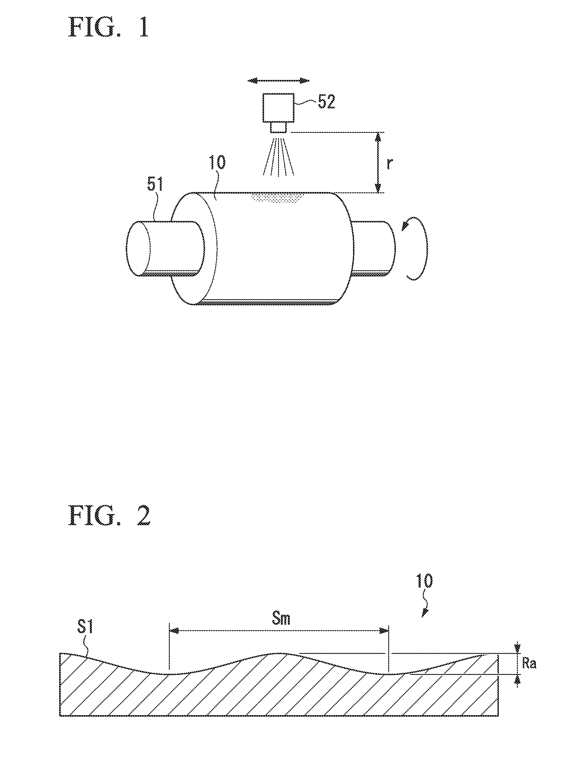
[0201]The surface of the obtained stamper was observed by an electron scanning microscope, and the dimensions of pores were measured. In addition, the surface of the obtained molded body was measured by a probe roughness meter, and the results were used as the arithmetic average roughness Ra and the period Sm of the stamper. The results are shown in Table 2.

[0202]Measurements and evaluations were performed on the obtained molded body in the same manner as Example 1. The results are shown in Table 2.

examples 3 and 4

[0203]Stampers were manufactured in the same manner as Example 1 except that blasting conditions were changed to those in Table 1. Molded bodies were manufactured in the same manner as Example 1 by using the obtained stampers.

[0204]The surfaces of the obtained stampers were observed by an electron scanning microscope, and the dimensions of pores were measured. In addition, the surfaces of the obtained molded bodies were measured by a probe roughness meter, and the results were used as the arithmetic average roughnesses Ra and the periods Sm of the stampers. The results are shown in Table 2. The results are shown in Table 2.

[0205]Measurements and evaluations were performed on the obtained molded bodies in the same manner as Example 1. The results are shown in Table 2.


PUM

PropertyMeasurementUnit
arithmetic average roughnessaaaaaaaaaa

Abstract

A method of manufacturing a stamper of the invention includes: performing a blast process on an aluminum base material, and thereafter anodizing a processing surface of the blast-processed aluminum base material so that a structure which includes a rough rugged structure having an specific arithmetic average roughness Ra and a specific period Sm and a fine rugged structure which is formed on the rough rugged structure to have a shorter period than that of the rough rugged structure is formed on a surface of the aluminum base material. In the stamper of the invention, by anodizing the processing surface of the blast-processed aluminum base material, the structure which includes the specific rough rugged structure and the fine rugged structure which is formed on the specific rough rugged structure to have a shorter period than that of the rough rugged structure is formed on the surface of the aluminum base material.

Description

TECHNICAL FIELD[0001]The present invention relates to a stamper, a method of manufacturing the same, and a method of manufacturing a molded body.[0002]Priority is claimed on Japanese Patent Application No. 2011-285652, filed on Dec. 27, 2011, the content of which is incorporated herein by reference.BACKGROUND ART[0003]Recently, for the purpose of applying antireflection properties, antifogging properties, antifouling properties, water repellency, and the like, a molded body such as a functional film having a fine rugged structure on the surface is suggested. Particularly, it is known that the fine rugged structure called a moth-eye structure exhibits excellent antireflection properties.[0004]As a method of forming the fine rugged structure on the surface of the molded body, there are a method of directly processing the surface of a material, a transfer method of using a stamper (mold) having an inverted structure corresponding to the fine rugged structure and transferring the struct...

Claims


Application Information

Patent Timeline
Patent Type & Authority Applications(United States)
IPC IPC(8): C25D11/16B24C1/04B24C11/00G02B1/11
CPCC25D11/16B24C11/00B24C1/04G02B1/11C25D11/04C25D11/045G02B1/111
Inventor SAIKI, ATSUSHIKUWAHARA, AYAKA
Owner MITSUBISHI RAYON CO LTD
Features
  • R&D
  • Intellectual Property
  • Life Sciences
  • Materials
  • Tech Scout
  • Unparalleled Data Quality
  • Higher Quality Content
  • 60% Fewer Hallucinations
Learn More