
Ophthalmic lens system capable of communication between lenses utilizing a secondary external devicece

Active Publication Date: 2015-03-05
JOHNSON & JOHNSON VISION CARE INC
View PDF7 Cites 48 Cited by
  • Summary
  • Abstract
  • Description
  • Claims
  • Application Information

AI Technical Summary

Benefits of technology

The patent text describes how adding a smartphone, watch, or tablet to an ophthalmic lens system can make communication easier. These external electronic devices have more battery power and communication capabilities than the lenses, so it's easier for them to communicate with each other. This reduces the electrical requirements on the contact lenses.

Problems solved by technology

Communication between two contact lenses on a user may be difficult for several reasons.
Thus, each contact lens may be limited in transmitter output power and receiver sensitivity.
Although the contact lenses may only be about 70 mm apart when on a user's eyes, there may not be a direct line of sight between the lenses, so direct light-based communication may not be possible without relying on reflections from nearby objects.
Further, in the event a radio frequency (RF) system may be used, the antenna area available in a contact lens, along with the dielectric properties of the eye and body, may make communication inefficient.
Complex processing of signals, decision inputs, and data may also be difficult in contact lenses.
The aforementioned limits on area, volume, and battery capacity may constrain the size, speed, computational complexity, and current consumption of a processor.
For example, while it may be preferred for application enablement to include a powerful microcontroller or central processing unit (CPU) in contact lenses, state-of-the-art technology may not allow such integration.
Further, this system may require tight timing synchronization between the lenses.
Similar techniques are used in cellular communications, where a user's handset has limited battery power and limited size, and thus limited transmitter and receiver power and antenna gain.
In such an example, the much larger available size and current in the cellular base station permits higher gain, power, and computational complexity.

Method used


Image

  • Ophthalmic lens system capable of communication between lenses utilizing a secondary external devicece
  • Ophthalmic lens system capable of communication between lenses utilizing a secondary external devicece
  • Ophthalmic lens system capable of communication between lenses utilizing a secondary external devicece

Examples


Embodiment Construction

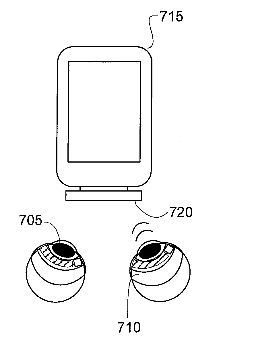
[0031]The present invention describes an ophthalmic lens system capable of wireless communication between ophthalmic lenses, wherein the wireless communication capabilities may be improved through use of an external device, which may offer larger volume capacity to house electronic components. In general, according to some exemplary embodiments of the present invention, the external device may be able to bear the majority of the processing and power burdens that may be associated with complex wireless communication. In addition, utilizing an external device may broaden the possible wireless communication methods, since an external device may allow for line-of-sight transmissions.

[0032]In the following sections, detailed descriptions of exemplary embodiments of the present invention will be given. The description of both preferred and alternative embodiments are exemplary embodiments only, and it is understood that to those skilled in the art that variations, modifications, and alter...


PUM


Abstract

The present invention comprises an ophthalmic lens system capable of wireless communication through utilization of an external device, wherein the ophthalmic lens system comprises a first ophthalmic lens on a first eye and a second ophthalmic lens on a second eye, wherein the lenses may be configured to wirelessly communicate with each other by transmitting and receiving data through an external device. More particularly, in some embodiments, the external device may comprise electronic components with more computational power and energization capabilities than the ophthalmic lenses.

Description

BACKGROUND OF THE INVENTION[0001]1. Field of the Invention[0002]The present invention relates to methods, apparatus, and devices associated with an ophthalmic lens system wherein the lenses may communicate with each other utilizing a secondary electronic external device. More particularly, the present invention relates to an ophthalmic lens system that may depend on the secondary electronic external device to reduce power, communication, and processing requirements within the ophthalmic lenses.[0003]2. Discussion of the Related Art[0004]Traditionally, an ophthalmic device, such as a contact lens, an intraocular lens, or a punctal plug included a biocompatible device with a corrective, cosmetic, or therapeutic quality. A contact lens, for example, may provide one or more of vision correcting functionality, cosmetic enhancement, and / or therapeutic effects. Each function may be provided by a physical characteristic of the lens. A design incorporating a refractive quality into a lens ma...

Claims


Application Information

Patent Timeline
IPC IPC(8): G02C7/04A61B3/113H04W4/50H04W4/80
CPCA61B3/113G02C7/049G02C7/04G02C7/081G06F3/013A61F2250/0002H04W4/50H04W4/80
Inventor TONER, ADAMPUGH, RANDALL BRAXTON
Owner JOHNSON & JOHNSON VISION CARE INC
Features
  • Generate Ideas
  • Intellectual Property
  • Life Sciences
  • Materials
  • Tech Scout
  • Unparalleled Data Quality
  • Higher Quality Content
  • 60% Fewer Hallucinations
Learn More