Catalytic Alkane Conversion and Olefin Separation

Active Publication Date: 2015-03-05
EXXONMOBIL CHEM PAT INC
View PDF0 Cites 55 Cited by
  • Summary
  • Abstract
  • Description
  • Claims
  • Application Information

AI Technical Summary

Benefits of technology

[0018]Other aspects of the invention further relate to a hydrocarbon conversion system for producing a C2 composition, which includes a reactor in fluid communication with a sorption system. The reactor comprises: (i) a first region having a first thermal mass and a first aperture, (ii) a second region having a second thermal mass and a second aperture, and (iii) a catalytic conversion zone containing catalyst having an oxidative coupling functionality, oxydehydrogenation functionality or both, with at least a portion of the catalyst being deposited on or in at least one of the first thermal mass and second thermal mass. The first and second regions are configured for flowing a feed mixture to enter the reactor proximate to the first aperture, with one or more components of a reaction mixture exiting the reactor proximate to the second aperture. A sorption system, which operates under kinetic sorption conditions, is configure

Problems solved by technology

Generating this heat and transferring it to the methane is a significant cost and can introduce inefficiencies into the process.
Although the disclosed moving-bed and gas-recycle processes improve conversion, the quenching is energy intensive, and further improvements are desired.
Separat

Method used


Image

  • Catalytic Alkane Conversion and Olefin Separation
  • Catalytic Alkane Conversion and Olefin Separation
  • Catalytic Alkane Conversion and Olefin Separation

Examples


example 1 (with reference to fig.1)

Example 1 (with Reference to FIG. 1)

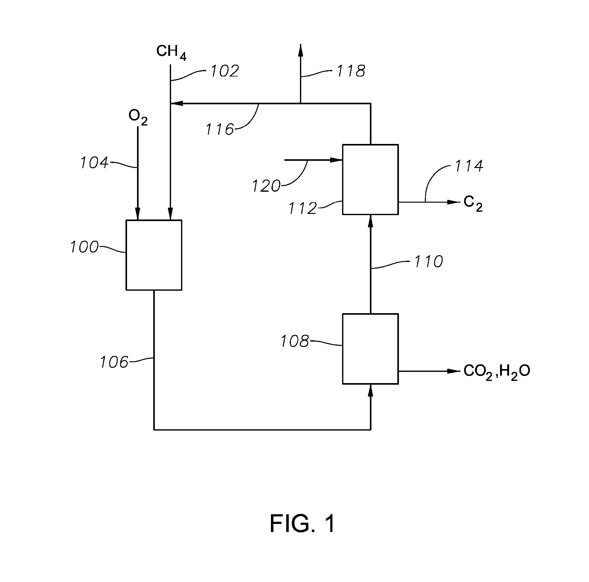
[0166]FIG. 1 depicts a generalized system for selectively removing the specified C2 composition according to certain aspects of the invention. Hydrocarbon conversion reactor 100 contains the specified hydrocarbon conversion catalyst, namely one having oxidative coupling and / or oxydehydrogenation functionality. A hydrocarbon reactant containing methane (CH4) is introduced into the hydrocarbon conversion reactor 100 via a line 102, and oxidant containing molecular oxygen (O2) is introduced via a line 104. At least a portion of the methane is catalytically converted to a reaction mixture comprising (i) a C2+ composition, including at least ethane and ethylene, and (ii) CO2 and / or water, and (iii) any unreacted methane. The reaction mixture exits the reactor via a line 106 and is sent to a first separation unit 108 for removing at least a portion of the CO2 and water. A CO2 lean and water lean stream exits the first separation unit via a line 110 and ...

example 2 (with reference to fig.2)

Example 2 (with Reference to FIG. 2)

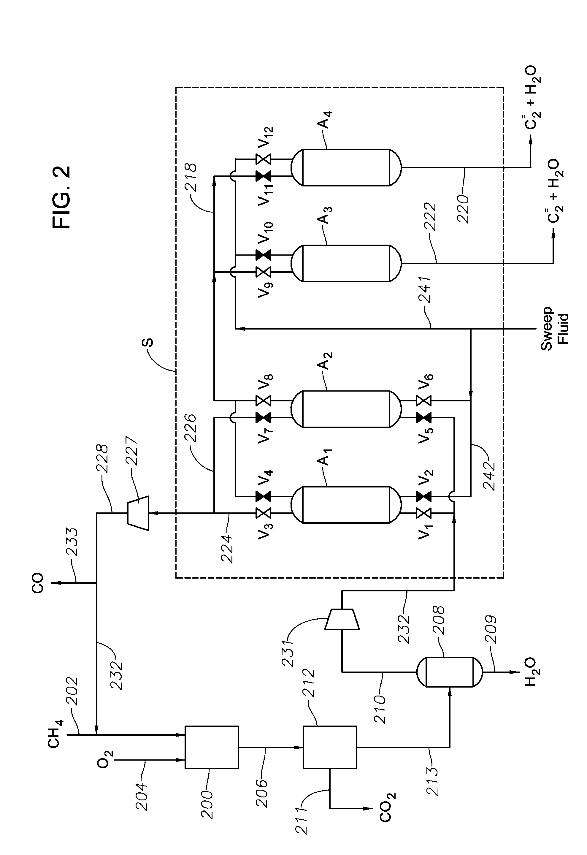
[0168]FIG. 2 depicts another generalized system for selectively removing a C2 composition according to certain aspects of the invention. Hydrocarbon conversion reactor 200 contains catalyst the specified hydrocarbon conversion catalyst. A hydrocarbon reactant containing methane (CH4) is introduced into the hydrocarbon conversion reactor 200 via a line 202, and oxidant containing molecular oxygen (O2) is introduced via a line 204. At least a portion of the methane is catalytically converted to a reaction mixture comprised of C2+ compositions, including at least ethane and ethylene, as well as CO2 and water, and further includes any unreacted methane. The reaction mixture exits the reactor via a line 206, and is sent to a CO2 separation unit 212 to selectively remove at least a portion of the CO2 via a line 211 (typically in the form of products of a CO2 conversion reaction). A CO2 lean stream exits the CO2 separation unit via a line 213 and is sent...

example 3 (with reference to figs.3a and 3b)

Example 3 (with Reference to FIGS. 3A and 3B)

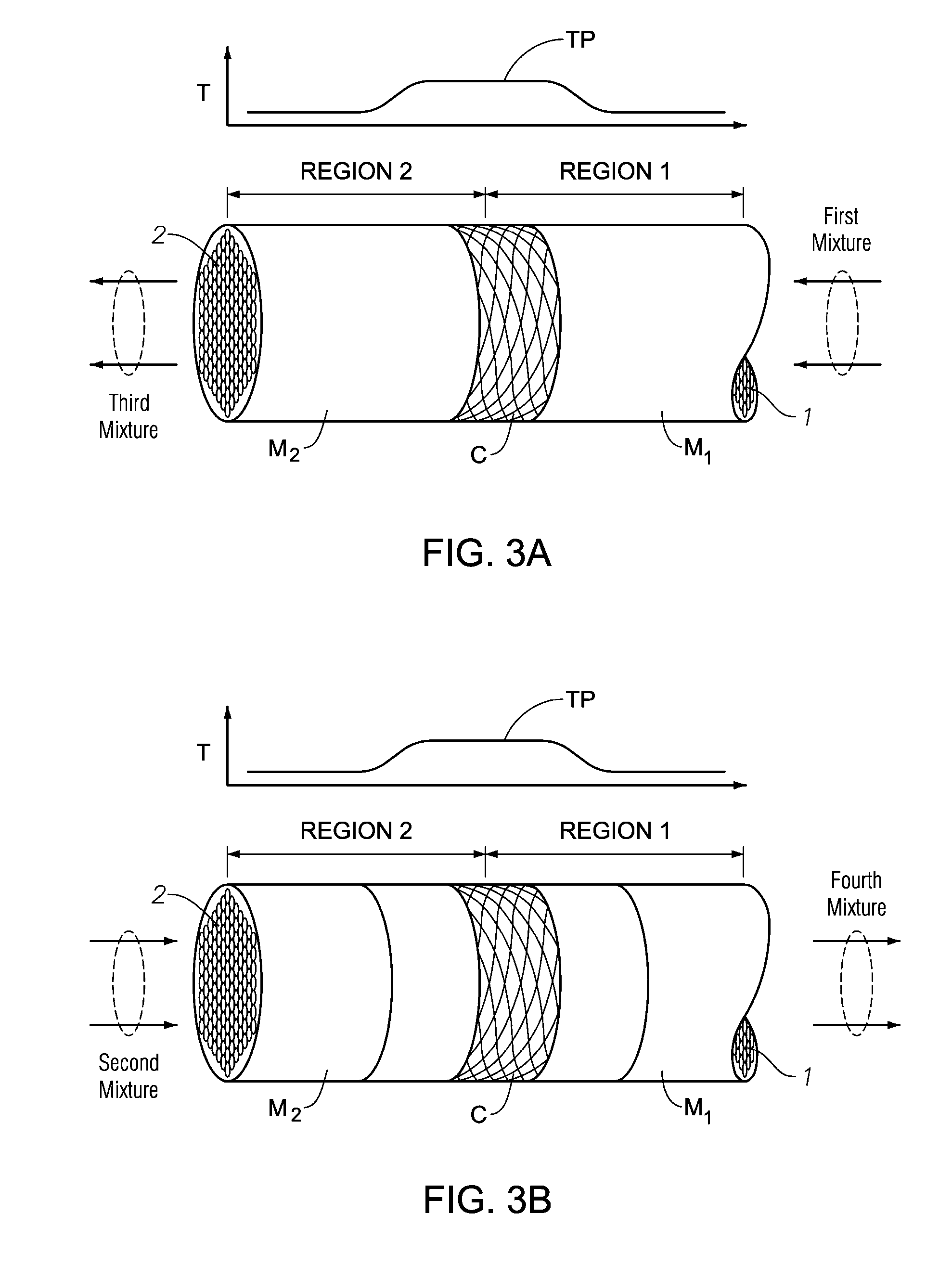
[0175]FIGS. 3A and 3B depict aspects of a generalized reverse-flow reactor system that can be used to carry out the specified conversion reaction. Such aspects can be used as the conversion reactors 100 and 200 of FIGS. 1 and / or 2.

[0176]The reverse-flow reactor includes two regions: a first region (Region 1) and a second region (Region 2). Region 1 and Region 2 comprise a first thermal mass (M1) and a second thermal mass (M2), respectively. The thermal masses can be selected from among any of the specified thermal masses, and can be coupled together as a continuous mass or coupled in a series arrangement of mass materials. The terms first and second thermal masses are used to particularly describe the flow of heat in the reverse-flow reactor system according to regions that are heated and cooled by means of thermal mass, such that the reaction being carried out results in absorption and release of heat in a manner that is effective in con...


PUM

PropertyMeasurementUnit
Fractionaaaaaaaaaa
Fractionaaaaaaaaaa
Fractionaaaaaaaaaa

Abstract

Disclosed is a hydrocarbon conversion process that is less energy intensive than comparable processes. The hydrocarbon conversion process is particularly desirable for converting alkanes, such as methane into C2+ olefins, such as ethylene and propylene, particularly with increasing selectivity to ethylene production. It is also desirable for effectively removing a C2 composition (i.e., ethane, ethylene and/or acetylene) produced from the catalytic conversion of hydrocarbon comprised of C2+ olefins. In addition, the hydrocarbon process is desirable for providing a substantially non-cryogenic separation of the desired C2 compositions from the hydrocarbons (e.g., methane) present in the reaction mixture.

Description

CROSS-REFERENCE TO RELATED APPLICATION[0001]This application claims priority to and the benefit of (i) U.S. Provisional Patent Application No. 61 / 872,175, filed Aug. 30, 2013; (ii) E.P. Patent Application No. 13189746.4, filed Oct. 22, 2013; the contents of which are incorporated herein by reference in their entireties. The following related cases are also incorporated by reference in their entireties: (i) P.C.T. Patent Application No. ______, (Docket No. 2014EM205PCT), filed Aug. 26, 2014; (ii) U.S. patent application Ser. No. ______, (Docket No. 2014EM205US), filed Aug. 26, 2014, (iii) P.C.T. Patent Application No. ______, (Docket No. 2014EM206PCT), filed Aug. 26, 2014; (iv) U.S. patent application Ser. No. ______, (Docket No. 2014EM206US), filed Aug. 26, 2014; (v) P.C.T. Patent Application No. ______, (Docket No. 2013EM242PCT), filed Aug. 26, 2014; (vi) U.S. patent application Ser. No. ______, (Docket No. 2013EM242 / 2US), filed Aug. 26, 2014; and (vii) U.S. patent application Ser....

Claims


Application Information

Patent Timeline
IPC IPC(8): C07C2/84C07C7/12
CPCC07C7/12C07C2/84B01J2208/00309B01J2208/0053B01J2208/00548B01J2208/00557B01J2208/00566B01J2219/2402B01D53/04B01D2256/24B01D2257/7022B01D2259/4009C07C2/78Y02P20/52B01J8/0207Y02P20/50C07C11/04C07C15/02C07C2/42B01J19/24B01J19/245B01J2219/24C07C2/08C07C5/48C07C7/005B01J15/005B01J8/0285B01J2208/00168B01J2208/02
Inventor HENAO, JUAN D.KEUSENKOTHEN, PAUL F.PATIL, ABHIMANYU O.
Owner EXXONMOBIL CHEM PAT INC
Why Eureka
Try Eureka