Joint estimation of attenuation and activity information using emission data

a technology of activity information and emission data, applied in the field of joint estimation of attenuation and activity information using emission data, can solve the problems of ct imaging having limited soft tissue contrast, deteriorating image quality, and inability to provide a direct transformation of magnetic resonance (mr) images into pet attenuation values

Inactive Publication Date: 2015-03-05
GENERAL ELECTRIC CO
View PDF4 Cites 29 Cited by
  • Summary
  • Abstract
  • Description
  • Claims
  • Application Information

AI Technical Summary

Problems solved by technology

However, during PET imaging, photon-electron interactions may result in attenuation of emitted photons, which in turn, may lead to degraded image quality and inaccurate PET quantitation.
However, CT imaging may have limited soft-tissue contrast and involve administration of substantial radiation to a patient.
MRI, however, may not provide a direct transformation of magnetic resonance (MR) images into PET attenuation values.
Although bones / metal implants and lungs / air have substantially different PET attenuation values, MRI typically does not discriminate well between bone / metal implants and air / lungs.
Use of conventional segmentation-based approaches for estimation of PET attenuation and activity, thus, may result in inaccurate attenuation correction, particularly in and / or near bones and lungs.
Moreover, conventional joint estimation approaches for reconstructing all voxels / pixels in PET attenuation and activity maps from only PET emission projection data may result in cross-talk artifacts and incorrect scaling, thus leading to inaccurate attenuation correction, because of under-determinedness and ill-conditionedness of the corresponding inverse problem.
Further, in certain scenarios, MRI may provide only a truncated field of view (FOV) and may not provide information corresponding to extra-patient components such as beds and coils.
The truncated part and the extra-patient components may contribute to photon attenuation, which may lead to degraded image quality and inaccurate PET quantitation.

Method used


Image

  • Joint estimation of attenuation and activity information using emission data
  • Joint estimation of attenuation and activity information using emission data
  • Joint estimation of attenuation and activity information using emission data

Examples


Embodiment Construction

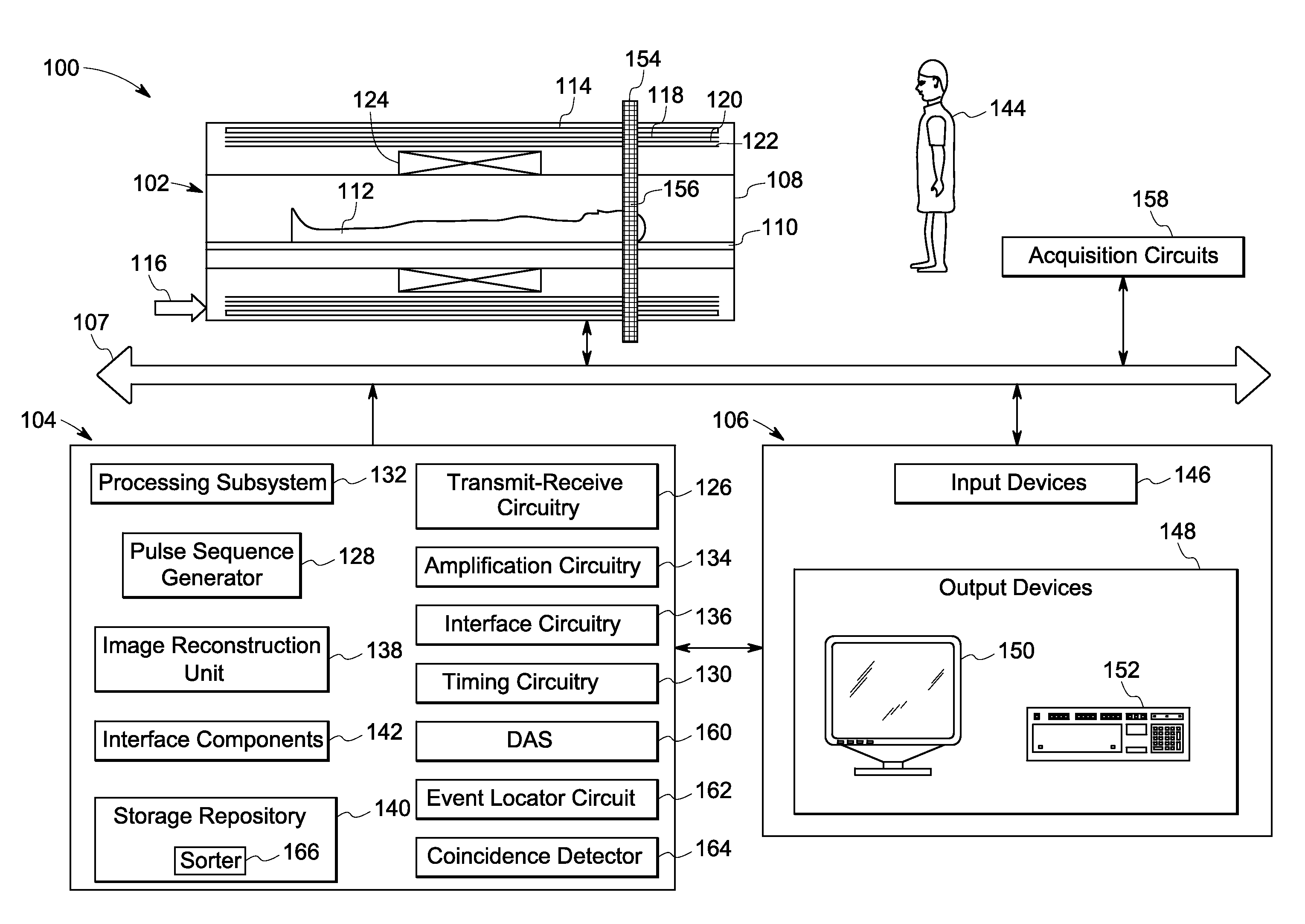
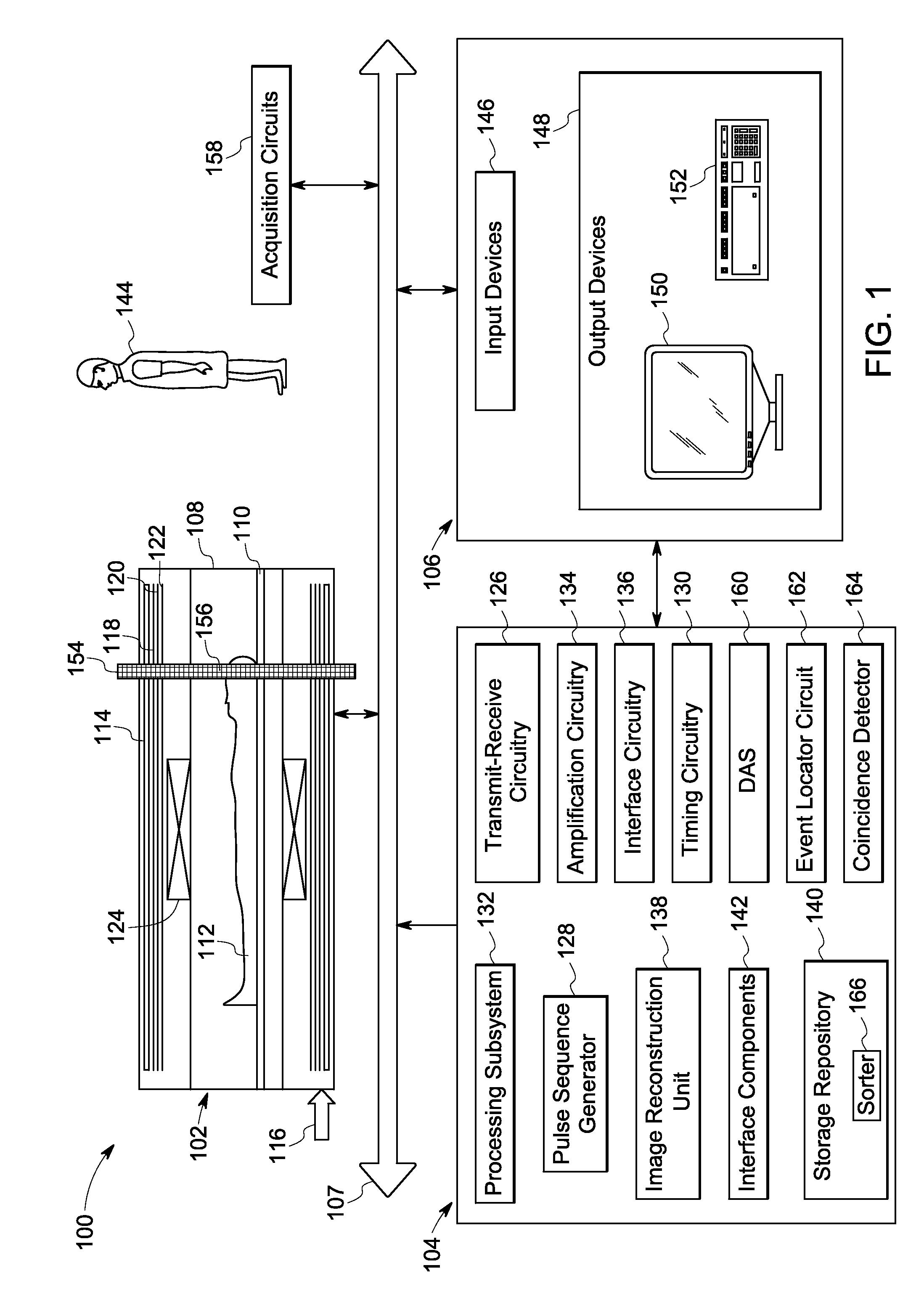
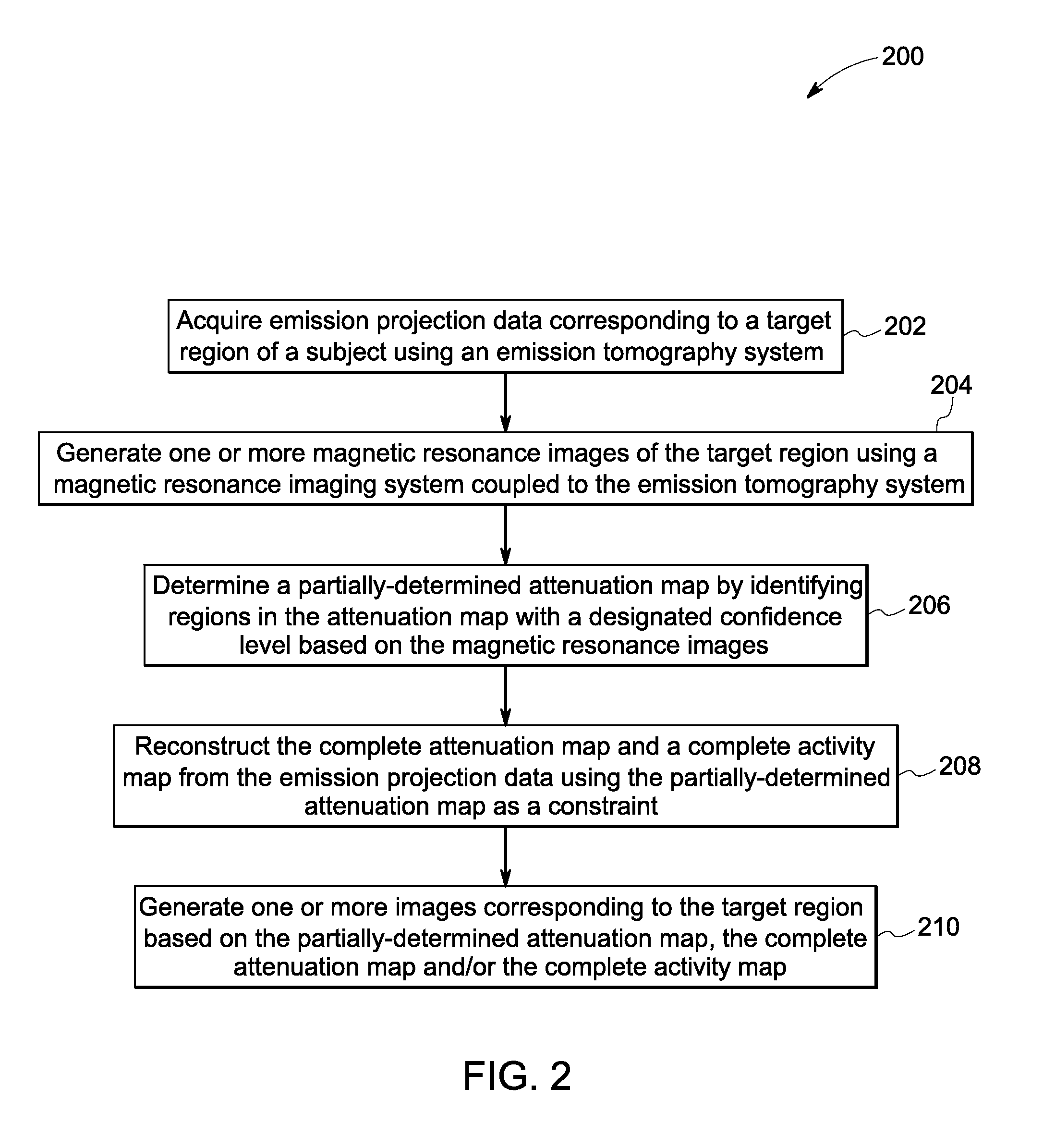
[0018]The following description presents exemplary systems and methods for attenuation correction in nuclear images using MR data. Particularly, embodiments illustrated hereinafter disclose hybrid PET / MRI systems and methods that allow for enhanced PET imaging by simultaneously generating an emission activity map and an attenuation map from emission data and a partially-determined attenuation map.

[0019]Although exemplary embodiments of the present technique are described in the context of correction of PET and / or PET / MR images, the approaches described herein are also applicable to attenuation correction and / or image modification in other modalities, such as single photon emission computed tomography (SPECT). Therefore, while hybrid PET / MR imaging is presently discussed, it should be noted that the disclosed techniques are also applicable to hybrid SPECT / MR, SPECT image modification and / or attenuation correction, and any other imaging modality in which attenuation correction or atte...


PUM


Abstract

Methods, systems and non-transitory computer readable media for imaging are disclosed. Emission projection data corresponding to a target region of a subject is acquired using an emission tomography system. Additionally, one or more magnetic resonance images of the target region are generated using a magnetic resonance imaging system operatively coupled to the emission tomography system. A partially-determined attenuation map is determined by identifying one or more regions in the partially-determined attenuation map with a designated confidence level based on the magnetic resonance images. Further, a complete attenuation map and/or a complete activity map is reconstructed from the emission projection data using the partially-determined attenuation map as a constraint. One or more images corresponding to the target region are then generated based on the partially-determined attenuation map, the complete attenuation map and/or the complete activity map.

Description

BACKGROUND[0001]Positron emission tomography (PET) finds use in generating images that represent a distribution of positron-emitting nuclides, for example, within a patient's body. During PET imaging, a radionuclide is injected into the patient. As the radionuclide decays, positrons are emitted that collide with electrons, resulting in an annihilation event, which converts the entire mass of the positron-electron pair into two 511 kilo-electron volt (keV) photons emitted in substantially opposite directions along a line of response (LOR). In a PET system, detectors placed along the LOR on a detector ring detect the annihilation photons. Particularly, the detectors detect a coincidence event if the photons arrive and are detected at the detector elements within a coincidence timing window. The PET system uses the detected coincidence information along with other acquired image data for ascertaining localized concentrations of the radionuclide for use in generating a functional diagno...

Claims


Application Information

Patent Timeline
Patent Type & Authority Applications(United States)
IPC IPC(8): A61B6/00G01R33/385A61B6/03G01R33/48
CPCA61B6/4417A61B6/037G01R33/385G01R33/481A61B6/5247
Inventor AHN, SANGTAEMANJESHWAR, RAVINDRA MOHAN
Owner GENERAL ELECTRIC CO
Why Eureka
Try Eureka