
Capacity control valve

a technology of capacity control valve and valve body, which is applied in the direction of positive displacement liquid engine, fluid pressure control, instruments, etc., can solve the problems of small yield stress of phosphor bronze, inability to ensure a long stroke, and phosphor bronze bellows tend to undergo characteristic changes, so as to improve the response reduce the diameter of the bellows and that of the valve element, and achieve the effect of greater yield stress

Inactive Publication Date: 2015-03-12
EAGLE INDS
View PDF40 Cites 20 Cited by
  • Summary
  • Abstract
  • Description
  • Claims
  • Application Information

AI Technical Summary

Benefits of technology

The patent text describes a pressure-sensitive body for a valve that has a reduced size and improved response, which can help make the valve lighter and more space-saving. This allows for a reduction in the size of the valve and a capacity control valve, which can be beneficial for the environment and improve durability. The pressure-sensitive body is made of a formed bellows made of material with greater yield stress than phosphor bronze, which can have its diameter set smaller and its stroke longer than the typical phosphor bronze bellows, to improve the response of the valve and reduce the size of the valve body. The formed bellows, adapter, and partition adjustment member are fixed by means of electron beam welding, which ensures good sliding property and improves the sensing accuracy. The bellows, adapter, and partition adjustment member are made of non-magnetic material, which makes the welding process easier and more reliable. Overall, this patent presents a technical solution for improving the performance and durability of valve components.

Problems solved by technology

This bellows 78A is made of phosphor bronze to achieve good workability, but from the viewpoint of spring property, phosphor bronze has a small yield stress as a material itself and cannot ensure a long stroke, and also a bellows made of phosphor bronze tends to undergo characteristic changes such as drop in load when an excessive pressure is applied or during use at high temperature, which makes it impossible to reduce the diameter or eliminate the coil spring 87.
To reduce the diameter of a phosphor bronze bellows, the thickness of the bellows must be increased and its length also increased in order to ensure long-enough stroke, meaning that a length dimension greater than the overall length of the current bellows is needed, which could result in poor formability and might also cause the bellows to project from the outer diameter dimension of the compressor because the overall length in the axial direction must be extended.

Method used


Image

  • Capacity control valve
  • Capacity control valve
  • Capacity control valve

Examples


Embodiment Construction

[0058]A mode for carrying out a capacity control valve pertaining to the present invention is explained in detail by referring to the drawings, but it should be noted that interpretations of the present invention are not at all limited to the following, and various changes, modifications, and improvements can be added based on the knowledge of those skilled in the art so long as they do not deviate from the scope of the present invention.

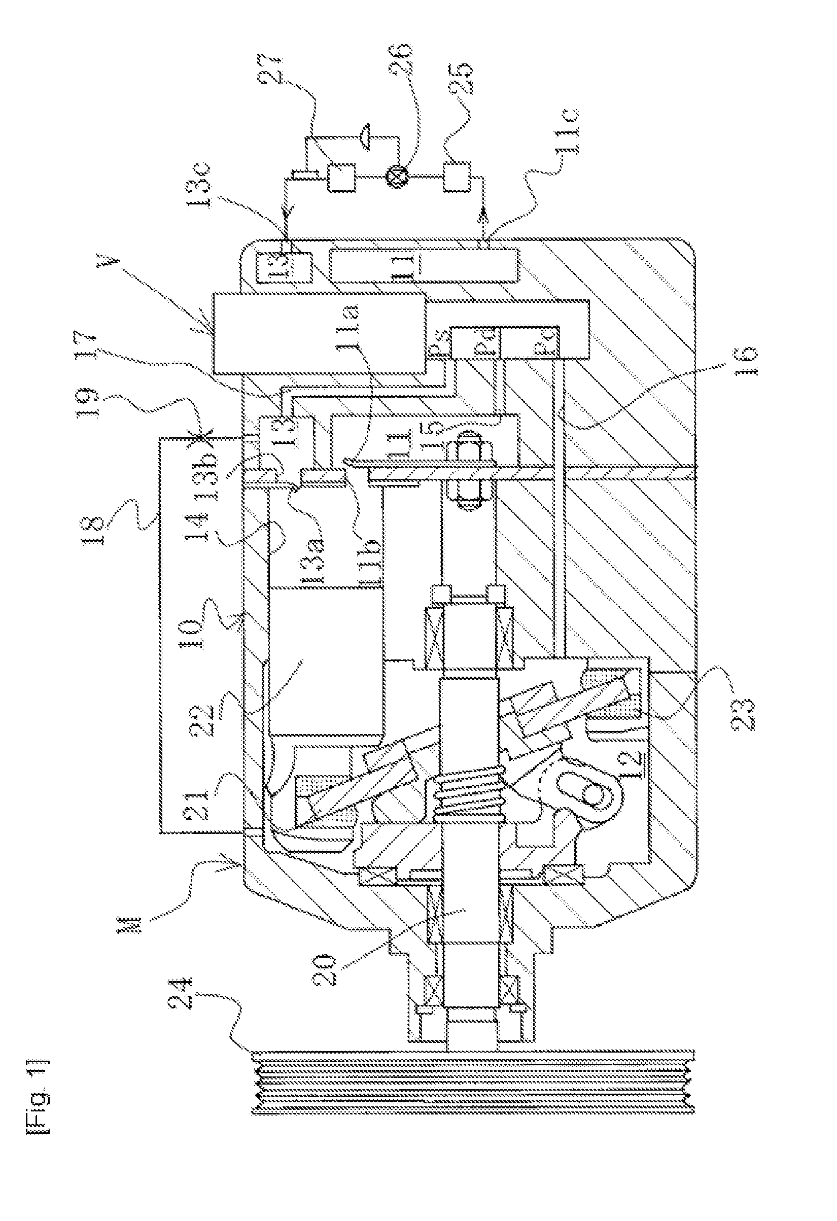
[0059]As shown in FIG. 1, a swashplate-type variable-capacity compressor M comprises, for example: a casing 10 that defines a discharge chamber 11, a control chamber (also referred to as “crank chamber”) 12, an intake chamber 13, multiple cylinders 14, a port 11b that communicates each cylinder 14 and the discharge chamber 11 and is opened / closed by a discharge valve 11a, a port 13b that communicates each cylinder 14 and the intake chamber 13 and is opened / closed by an intake valve 13a, a discharge port 11c and intake port 13c connected to an extern...


PUM


Abstract

In an embodiment, a capacity control valve includes: a pressure-sensitive body 50 positioned in a third valve chamber 38; an adapter 53 provided on the free end of the pressure-sensitive body 50 having a circular seating surface; a third valve part 43 that moves integrally with a valve element 40 in the third valve chamber 38 and has a circular engagement surface that opens / closes intake-side passages 34 by engaging with and separating from the seating surface of the adapter 53; and a solenoid 60 that applies an electromagnetic drive force to the valve element 40 in the direction of closing a first valve part 41, wherein the pressure-sensitive body 50 is formed by a formed bellows made of material having greater yield stress than phosphor bronze, and the formed bellows has its diameter set smaller and its stroke longer than the diameter and stroke of a phosphor bronze bellows.

Description

TECHNICAL FIELD[0001]The present invention relates to a capacity control valve that variably controls the capacity or pressure of working fluid, and specifically to a capacity control valve that controls the discharge rate of a variable-capacity compressor, etc., used for an automobile air-conditioning system, etc., according to the pressure load.BACKGROUND ART[0002]A swashplate type variable-capacity compressor used for an automobile air-conditioning system, etc., comprises, for example, a rotational axis driven by the rotational force of an engine to turn; a swashplate connected to the rotational axis in a manner allowing for change in its inclination angle relative to the rotational axis; and a compression piston connected to the swashplate, wherein the inclination angle of the swashplate is changed to change the stroke of the piston and thereby control the discharge rate of refrigerant gas.[0003]This inclination angle of the swashplate is continuously changed by utilizing the in...

Claims


Application Information

Patent Timeline
IPC IPC(8): F16K31/06F16K11/07
CPCF16K11/0716F16K31/0613G05D16/0619F04B27/1804G05D16/2024Y10T137/86622
Inventor IWA, TOSHIAKIOGAWA, YOSHIHIROFUKUDOME, KOHEIMORIWAKI, KENJI
Owner EAGLE INDS
Learn More