Power tool

Active Publication Date: 2015-03-12
MAKITA CORP
View PDF16 Cites 52 Cited by
  • Summary
  • Abstract
  • Description
  • Claims
  • Application Information

AI Technical Summary

Benefits of technology

[0016]According to the present teachings, a compact power tool can be achieved by using

Problems solved by technology

Although electric motors for light (low) load power tools may have a small size and thus be space saving, generally speaking such electric motors are not capable of drawing (or being driven by) a large current, thereby limiting their applicability.
In contr

Method used


Image

  • Power tool
  • Power tool
  • Power tool

Examples


Embodiment Construction

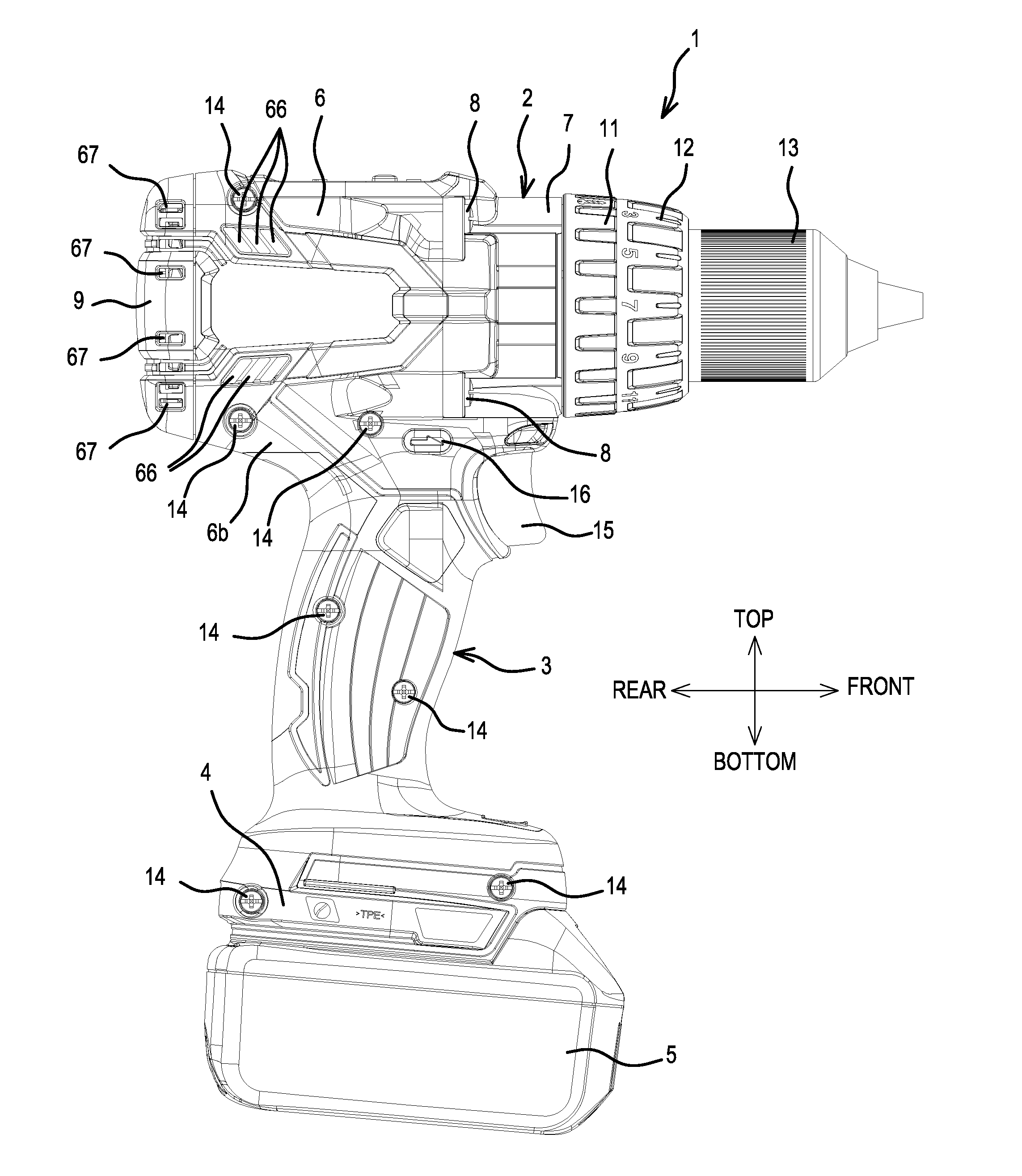
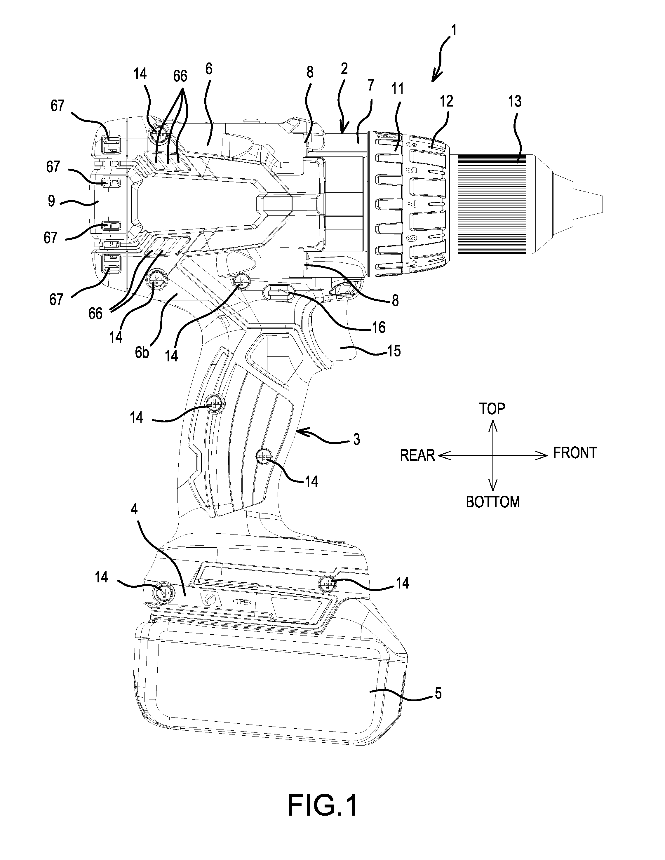
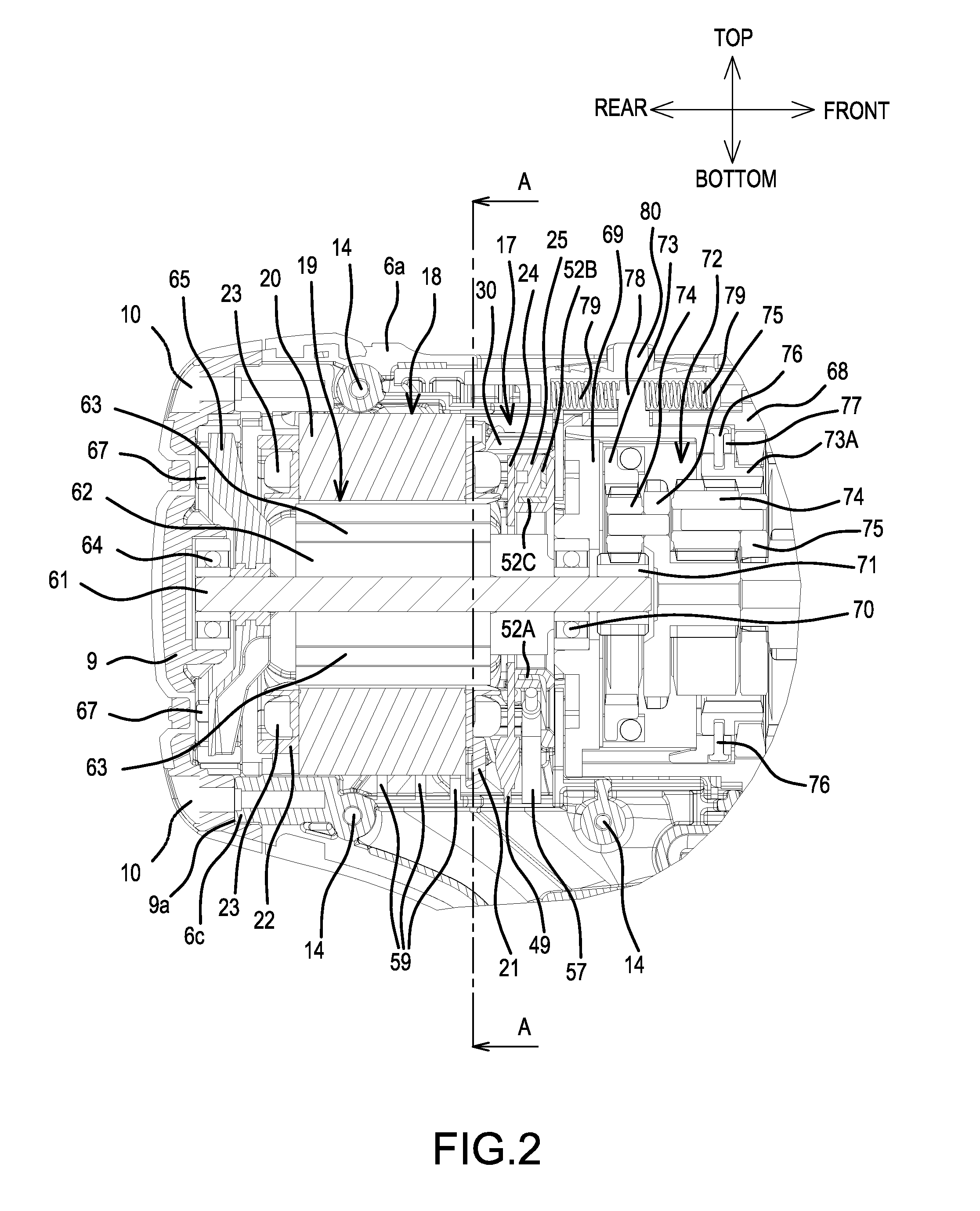
[0040]FIG. 1 is an overall view of a driver-drill 1, which serves one representative, non-limiting example of a power tool according to the present teachings. FIG. 2 is a longitudinal cross sectional view of a rear part of a main body 2 of the driver-drill 1. The representative driver-drill 1 has an overall T shape in that a handle 3 extends in a downward (substantially perpendicular) direction from the main body 2, which extends in a rear-front direction. Furthermore, a battery pack 5 constitutes a power supply for the driver-drill 1 and is mounted on a mounting part 4, which is formed at a lower end of the handle 3.

[0041]A housing of the main body 2 is formed by assembling (mounting) a front housing 7, which houses (surrounds or encloses, at least substantially) a clutch mechanism and a spindle, onto the front (i.e., the right side in FIG. 1) of a tubular main body housing 6, which houses a brushless motor 17 and a planetary gear speed reducing mechanism 72 that are discussed belo...


PUM


Abstract

A power tool (1; 90) includes a motor (17) having a stator (18) and a rotor (19). The stator (18) includes front and rear insulators (21, 22) respectively disposed forward and rearward of a stator core (20) in an axial direction thereof. At least six coils (23) are respectively wound on the stator (18) such that the coils (23) are wound through the front and rear insulators (21, 22). Winding wires (23a) respectively electrically connect circumferentially-adjacent pairs of the coils (23). A short circuiting device (25) short circuits respective pairs of windings (23a) that are located diagonally or diametrically across from one another.

Description

CROSS-REFERENCE[0001]The present application claims priority to Japanese patent application serial number 2013-188528 filed on Sep. 11, 2013, the contents of which are incorporated fully herein.TECHNICAL FIELD[0002]The present invention relates to a power tool, such as a driver-drill, that comprises a motor serving as its drive source.BACKGROUND ART[0003]As disclosed, e.g., in US 2011 / 0043057 A1 (and its family member JP 2011-45201 A), power tools equipped with a motor, such as a brushless motor, are well known. However, the overall structure of the electric motor differs depending on the model (e.g., a light load model or a heavy load model) of the power tool.[0004]For example, an electric motor for a light load model typically has a structure wherein the main current flows to a sensor circuit board via a solderable wire. On the other hand, in an electric motor for a heavy load model, lead wires (i.e., power supply wires) are typically directly connected to more robust fusing termi...

Claims


Application Information

Patent Timeline
IPC IPC(8): H02K7/14H02K11/00H02K3/38H02K3/28
CPCH02K7/145H02K3/38H02K11/0015H02K3/28H02K3/52H02K3/522H02K5/225H02K2203/03H02K2203/09H02K29/08H02K7/116H02K11/215H02K11/27B25F5/008H02K5/04B25F5/02B25F5/00
Inventor NAGAHAMA, TATSUYALNUZUKA, JUNYAMOMOSE, TAKASHI
Owner MAKITA CORP
Why Eureka
Try Eureka