Substrate embedded horn antenna having selection capability of vertical and horizontal radiation pattern

a horn antenna and substrate technology, applied in the field of horn antennas, can solve the problems of difficult communication between chips, large horn antennas, and inability to apply to mobile devices

Active Publication Date: 2015-03-12
KOREA ADVANCED INST OF SCI & TECH
View PDF3 Cites 204 Cited by
  • Summary
  • Abstract
  • Description
  • Claims
  • Application Information

AI Technical Summary

Problems solved by technology

However, most horn antennas are too big to apply to a mobile device.
Because of the directivity of the horn antenna having high gain, to use the horn antenna in the mobile device and communication between chips is very difficult.

Method used


Image

  • Substrate embedded horn antenna having selection capability of vertical and horizontal radiation pattern
  • Substrate embedded horn antenna having selection capability of vertical and horizontal radiation pattern
  • Substrate embedded horn antenna having selection capability of vertical and horizontal radiation pattern

Examples


first example embodiment

A First Example Embodiment

[0069]FIG. 3A is a diagram illustrating a direction of an electric field and a structure of a transfer part in a substrate embedded horn antenna according to an example embodiment.

[0070]Referring to FIG. 3A, the substrate embedded horn antenna may further include a feeding line, a resonance line and a via.

[0071]The feeding line 910 may be placed in the upper side of the dielectric and separated from the ground plate. The resonance line 930 may be connected to a top layer of the metal patterns and the resonance line may have a length of λ / 4, the λ may be a wave length of a transfer signal.

[0072]The via 920 may connect the feeding line 910 and the resonance line 930. The signal may be applied by providing the transfer signal to a waveguide 940 implemented on a substrate and converting a TEM mode to TE01 mode.

[0073]By connecting the feeding line as a microstrip or a coplanar waveguide 910 to the metal via 920 and the resonance line 930, the signal may be trans...

second example embodiment

A Second Example Embodiment

[0094]FIG. 6A is a perspective diagram illustrating a vertical radiation antenna and a horizontal radiation antenna according to another example embodiment.

[0095]Referring to FIG. 6A, method of integrating the substrate embedded horn antenna capable of selectively using the vertical radiation 1320 and the horizontal radiation 1310 in the substrate is illustrated in FIG. 6A. The substrate embedded horn antenna capable of selectively using the vertical radiation and the horizontal radiation may include the horn antenna 1410 vertically embedded in the substrate and the horn antenna 1420 horizontally embedded in the substrate 1430 where the vertical embedded horn antenna is placed.

[0096]The substrate embedded horn antenna includes a dielectric, a plurality of metal patterns, a plurality of metal vias and a ground plate. The plurality of metal patterns is embedded by being stacked in the dielectric. The plurality of metal patterns is hollow rectangle types or h...

third example embodiment

A Third Example Embodiment

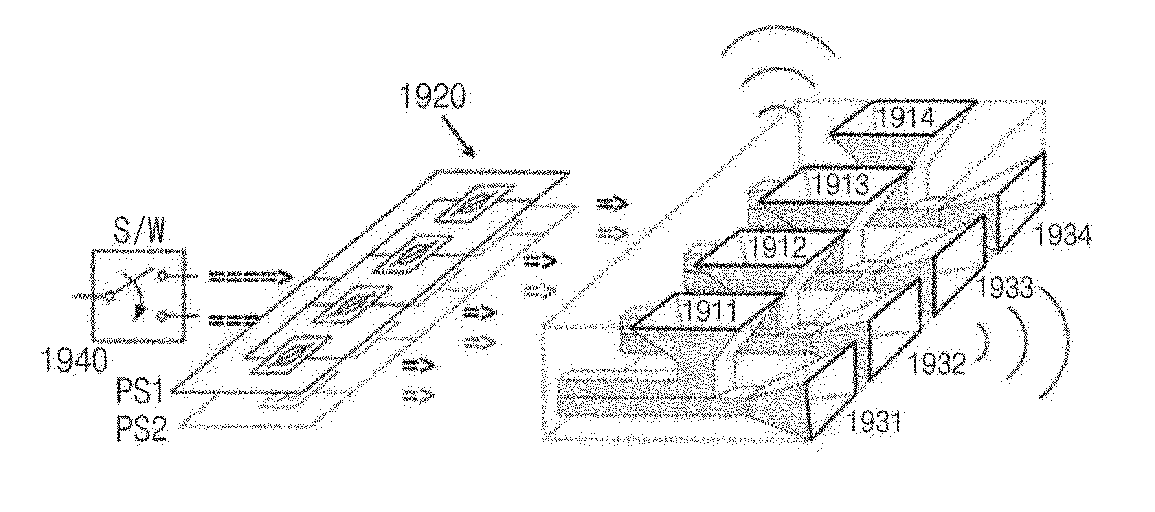
[0102]FIG. 7A is a diagram illustrating a switch connection to substrate embedded antennas capable of radiating by selecting a direction of an upper side, a direction of a front side, a direction of a left side and a direction of a right side according to still another example embodiment.

[0103]Referring to FIG. 7A, the substrate embedded horn antenna may include the horizontal embedded horn antennas and the vertical embedded horn antenna. The horn antennas may be horizontally embedded in a same layer of the substrate. The horizontal embedded horn antennas may be placed in a direction of a front side, a direction of a left side and a direction of a right side. The horn antenna may be vertically embedded in the same substrate where the horizontal embedded horn antennas are placed. The horizontal embedded horn antennas and the vertical embedded horn antenna may be selectively operated.

[0104]The substrate embedded horn antenna includes a dielectric, a plurality...


PUM


Abstract

Substrate embedded horn antenna includes a dielectric, metal patterns, metal vias and a ground plate. The metal patterns are embedded by being stacked in dielectric. Metal patterns are hollow rectangle types or hollow circle types. Metal vias connect layers of metal patterns by being embedded between layers of metal patterns. Ground plate is formed in an upper side of dielectric. Metal patterns form waveguide structure by being stacked in radial shape. Waveguide structure propagates electromagnetic wave by focusing electromagnetic wave. Embedded horn antenna capable of selectively using vertical radiation and horizontal radiation may be implemented using the via and metal pattern in dielectric substrate. Embedded horn antenna may be implemented in small size with high gain. Vertical embedded horn antenna and horizontal embedded horn antenna may be implemented in a substrate. Method of manufacturing embedded horn antenna capable of selectively using vertical radiation and horizontal radiation may be provided.

Description

CROSS-REFERENCE TO RELATED APPLICATION[0001]This application claims priority under 35 U.S.C. §119 to Korean Patent Application No. 10-2013-0109677, filed on Sep. 12, 2013, in the Korean Intellectual Property Office (KIPO), the contents of which are herein incorporated by reference in their entirety.BACKGROUND[0002]1. Technical Field[0003]Example embodiments relate generally to horn antenna capable of selectively using a horizontal radiation and a vertical radiation and more particularly to the horn antenna capable of selectively using the horizontal radiation and the vertical radiation by vertically or horizontally embedding the horn antenna in a same substrate.[0004]2. Description of the Related Art[0005]For a high speed data communication using millimeter wavelength and a wireless communication between communication chips, researches for various antennas are still going on. Low power consumption is required for the high speed data communication and the wireless communication. For ...

Claims


Application Information

Patent Timeline
Patent Type & Authority Applications(United States)
IPC IPC(8): H01Q13/02H01Q3/36H01Q3/24
CPCH01Q13/02H01Q3/36H01Q3/24H01L2223/6677H01L2224/16227H01L2224/48227H01L2924/15153H01L2924/15313H01Q13/0283H01Q21/08H01Q21/20
Inventor PARK, CHUL SOONKIM, HONG YI
Owner KOREA ADVANCED INST OF SCI & TECH
Why Eureka
Try Eureka