Electro-optic modulator and electro-optic distance-measuring device

Active Publication Date: 2015-03-12
LEICA GEOSYSTEMS AG
View PDF2 Cites 8 Cited by
  • Summary
  • Abstract
  • Description
  • Claims
  • Application Information

AI Technical Summary

Benefits of technology

[0062]When packaged, the modulator can generate microwave resonance in the case housing. Microwave absor

Problems solved by technology

Setting a particular modulation frequency requires mechanical tuning of the resonator, thus limiting the measurement rate (to e.g. 20 Hz).
However, since the measureme

Method used


Image

  • Electro-optic modulator and electro-optic distance-measuring device
  • Electro-optic modulator and electro-optic distance-measuring device
  • Electro-optic modulator and electro-optic distance-measuring device

Examples


Embodiment Construction

[0070]In principle, identical parts are provided with the same reference symbols in the Figures.

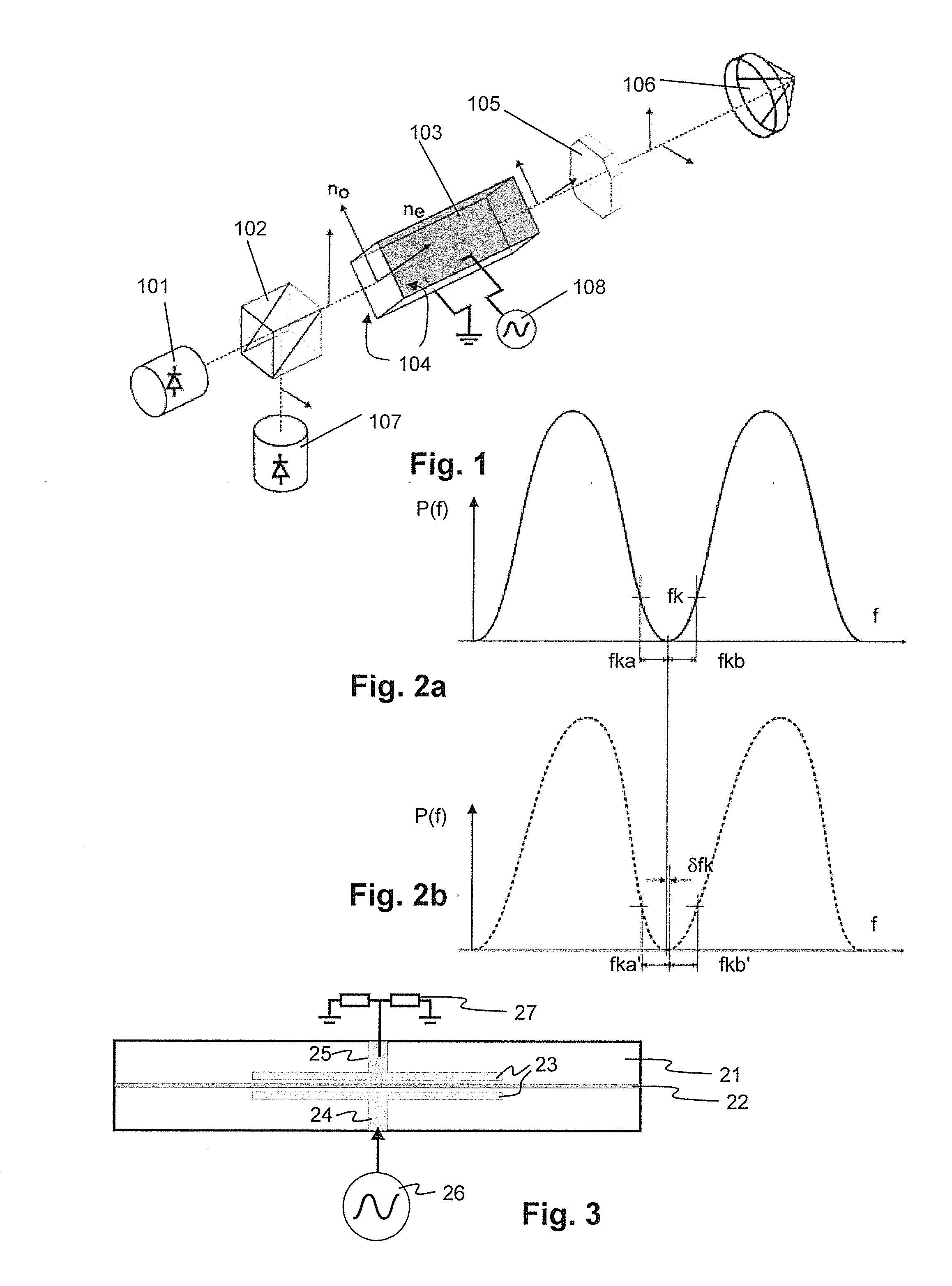
[0071]Convention: A phase modulator uses an electro-optic crystal. The index of modulation will define the so-called half wave voltage Vπ. The half-wave voltage is a characteristic of an electro-optic modulator and corresponds to the voltage that needs to be applied to the crystal in order to modify the optical phase of transmitted light by π-radians.

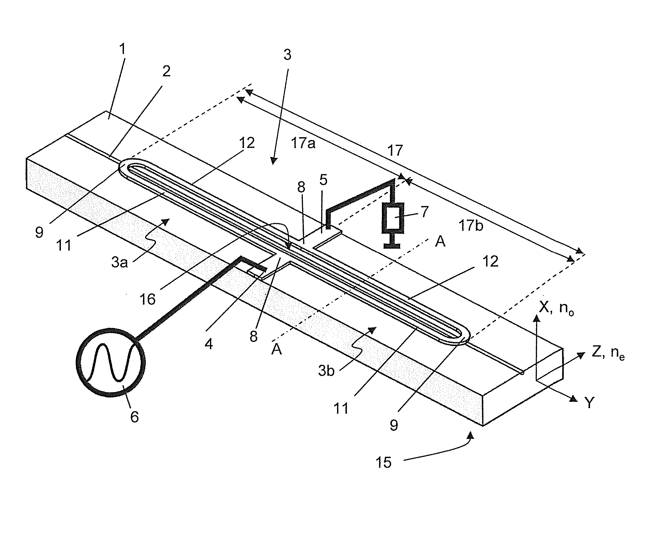
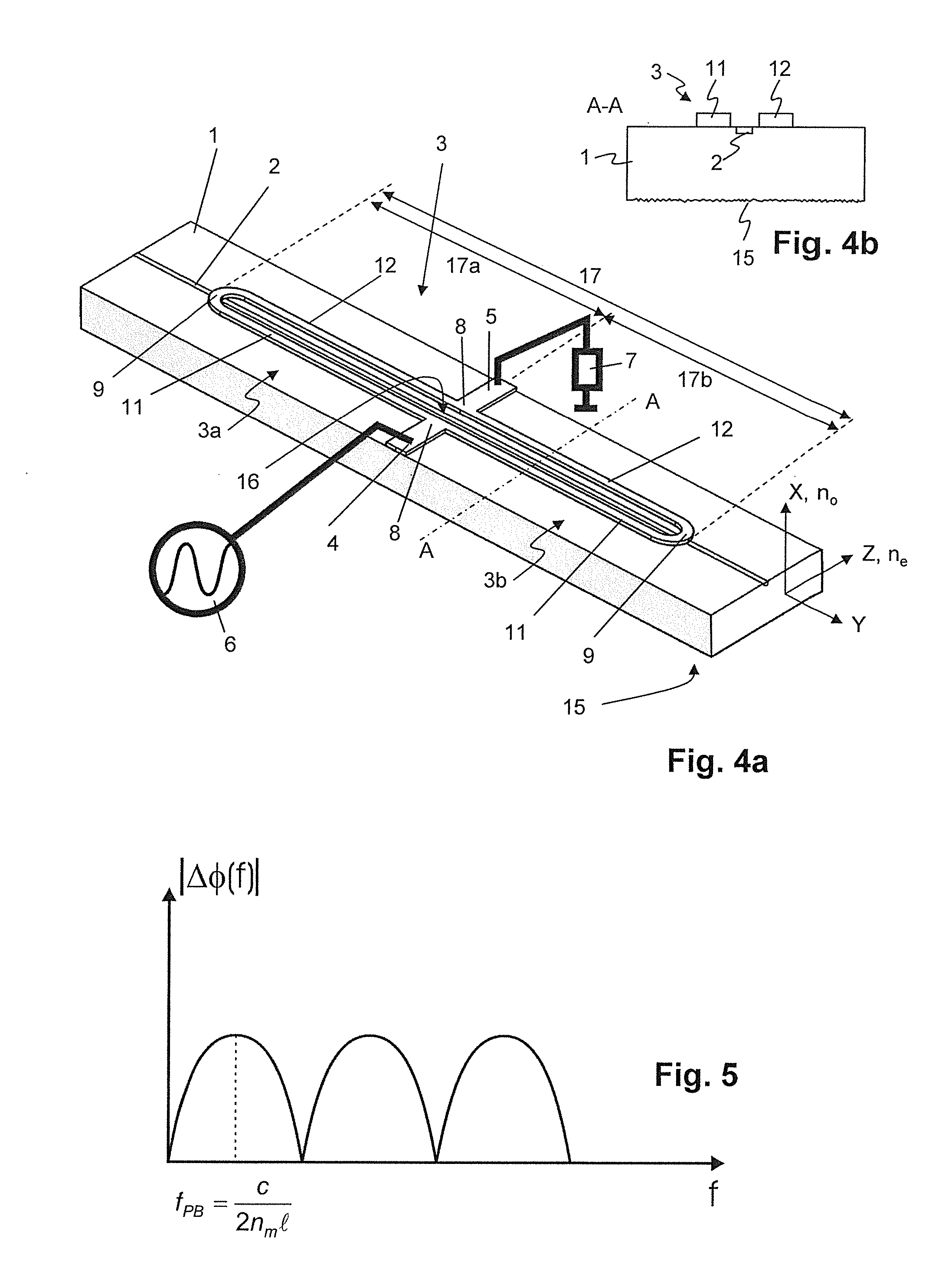
[0072]A guided wave configuration of an electro-optic modulator is as follows: a straight optical waveguide is shaped in a crystal surface, allowing the confinement of light in a small channel whose cross section is of some micrometers in width and height. Coplanar electrodes are arranged near the waveguides with a gap of some micrometers, application of a strong electric field to the waveguide. The half wave voltage can reduced to a few volts, much less than for bulk crystal modulators.

[0073]Guided wave modulators in, e.g. lithium niobate, c...


PUM


Abstract

An electro-optic modulator includes a waveguide of a nonlinear optical material and an electrode line for generating an electrical field in a modulating region of the waveguide when a voltage is applied to the electrode line, thereby modulating light passing through the waveguide. Therein, the forward electro-optic response of the modulating region is the same as the backward electro-optic response; and the electro-optic response has a band-pass or a low-pass characteristic. A distance measuring device includes a light source emitting light, and such an electro-optic modulator arranged such that the emitted light passes through the electro-optic modulator in a first direction before being emitted from the distance measuring device, and after being reflected from a target passes through the electro-optic modulator in a second direction which is opposite to the first direction.

Description

BACKGROUND OF THE INVENTION[0001]1. Field of the Invention[0002]The invention relates to an electro-optic modulator and to an electro-optic distance measuring.[0003]2. Description of Related Art[0004]U.S. Pat. No. 5,129,017, U.S. Pat. No. 5,050,948, U.S. Pat. No. 5,138,480, U.S. Pat. No. 5,278,924, WO02097526 and JP 9236783 A disclose integrated (coplanar waveguide or CPW) optics modulators with travelling wave electrodes. The modulators are structured as Mach-Zehnder-Modulators, that is, a beam of light is split up into two parts, one part of the light is phase modulated, the two parts are rejoined, and as a result the amplitude of the rejoined parts is modulated in accordance with the phase modulation. The light takes a single pass through the modulator, that is, in one direction only.[0005]Investigations on short path length high speed optical modulators in LiNbO3 with resonant type electrodes, R. Krahenbiihl, M. M. Howerton, Journal of Lightwave Technology, Vol. 19, No. 9 pp. 12...

Claims


Application Information

Patent Timeline
IPC IPC(8): G02F1/225G01S17/32G01B11/14G02F1/365G01B9/02
CPCG02F1/2255G02F1/365G01S17/32G01B11/14G01B9/02049G02F1/0316G02F1/0356G01S17/36G01S7/4812
Inventor PORTE, HENRIMOTTET, ALEXANDRELUTHI, THOMASBOCKEM, BURKHARD
Owner LEICA GEOSYSTEMS AG
Why Eureka
Try Eureka