
Unwanted plant removal system

a plant removal and unwanted technology, applied in the field of unwanted plant removal system, can solve the problems of undesirable plants or weeds, unfriendly environment, expensive or time-consuming human intervention,

Active Publication Date: 2015-03-19
XEROX CORP
View PDF8 Cites 24 Cited by
  • Summary
  • Abstract
  • Description
  • Claims
  • Application Information

AI Technical Summary

Benefits of technology

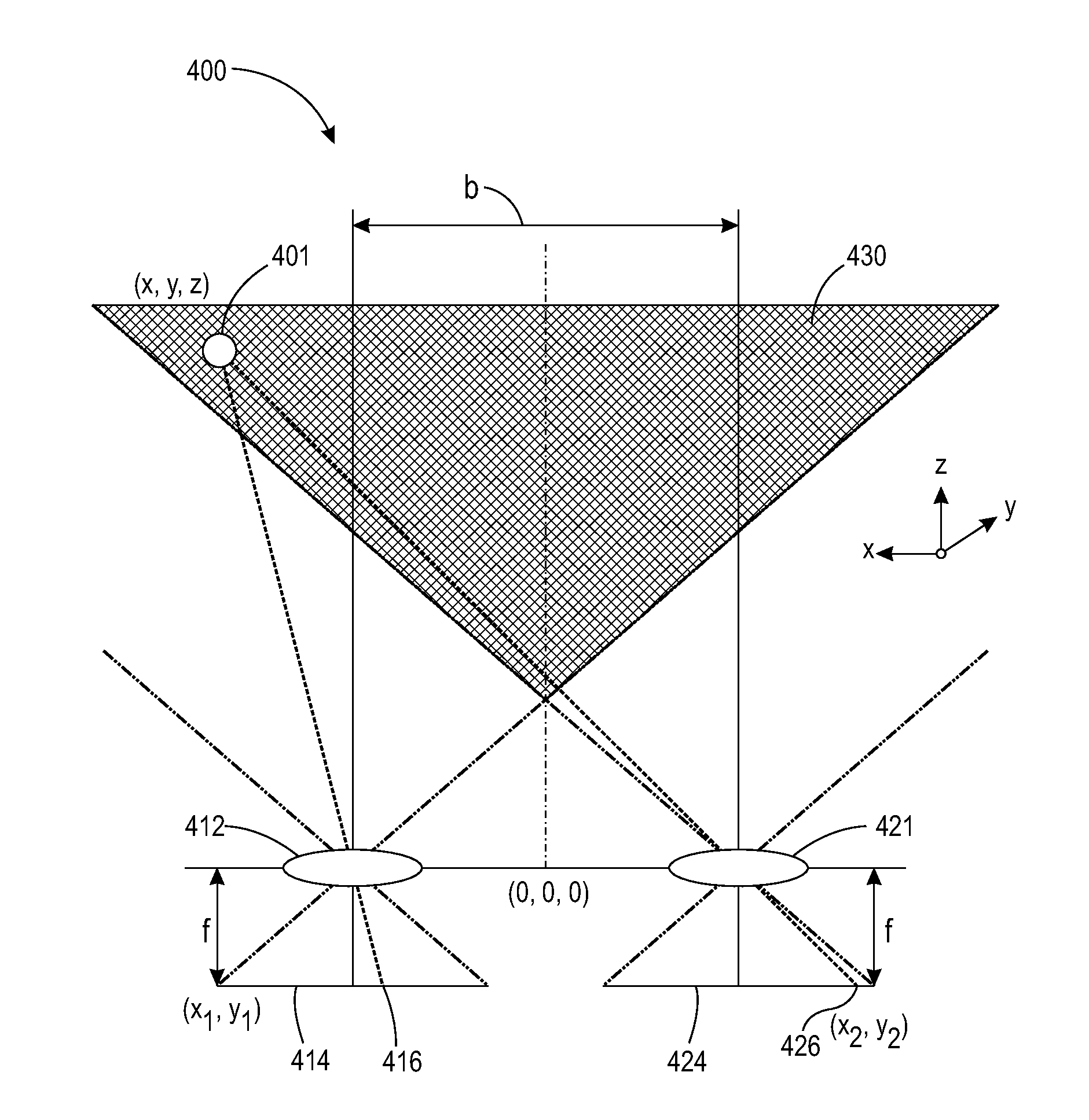
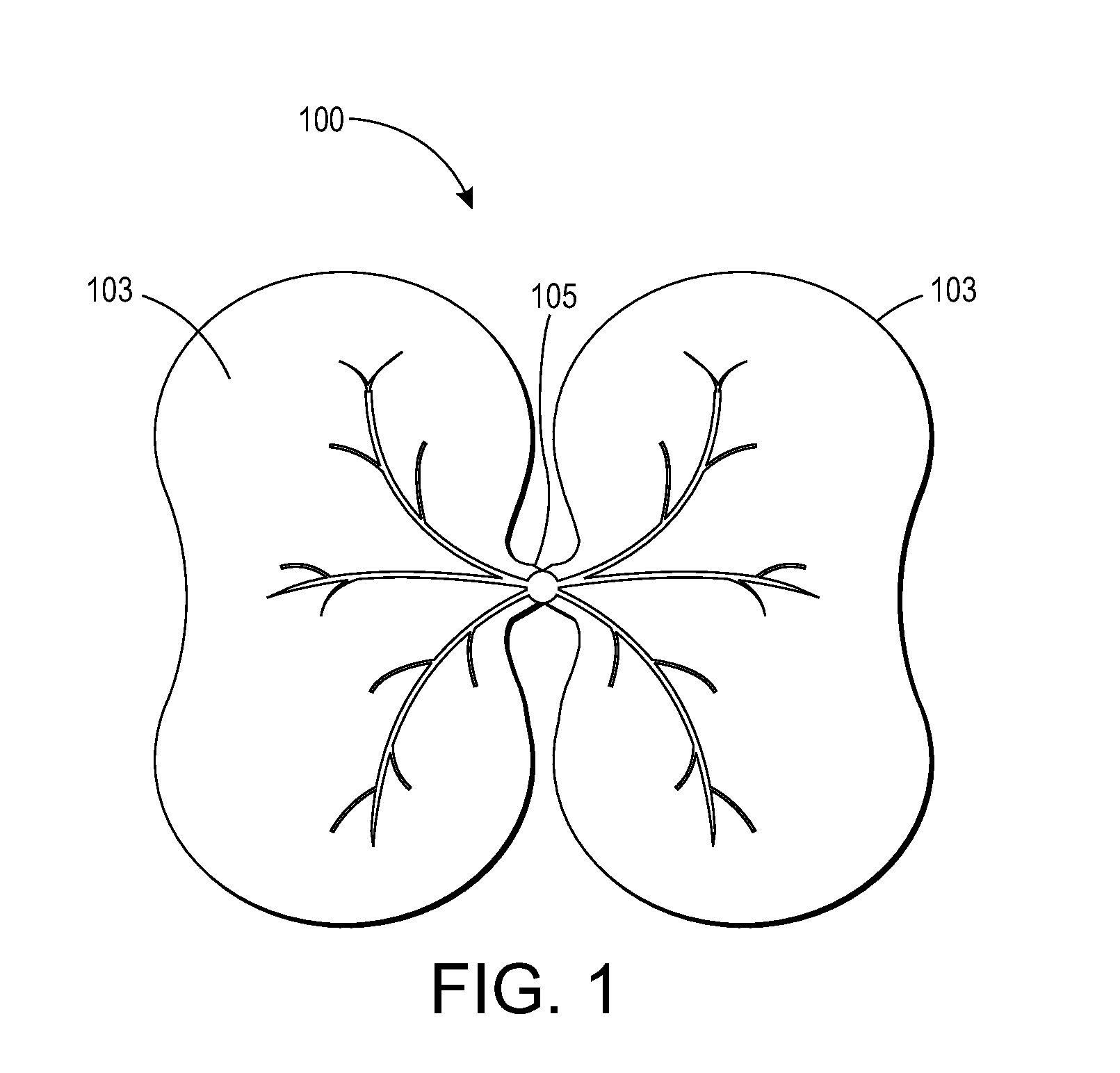
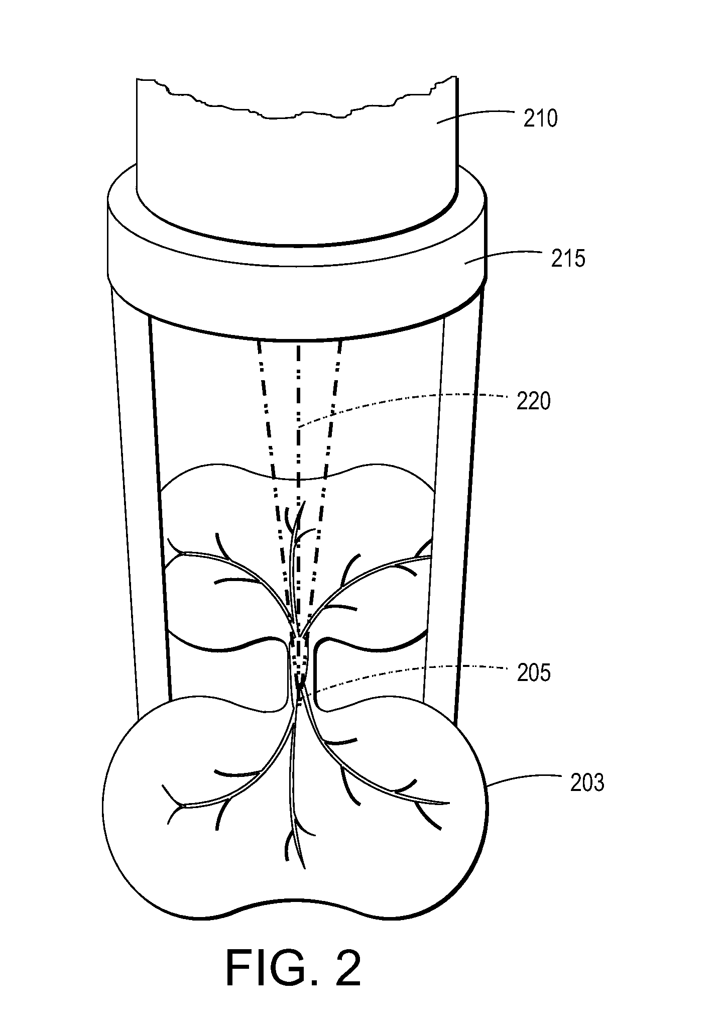
The patent text describes an apparatus and method for effectively and practically removing unwanted plants using low cost semiconductor lasers and new technology. The apparatus includes a three-dimensional imager to capture plant images and location, an image processor to distinguish between wanted and unwanted plants, a laser device to damage the unwanted plant, and a laser beam controller to direct the laser beam towards the unwanted plant. The method involves capturing plant images, identifying unwanted plants, guiding a laser beam towards the unwanted plant, and damaging it. The technology can be used in lawn weeding and other practical applications.

Problems solved by technology

Removal of undesirable plants or weeds is a problem that has been plaguing agriculture and horticulture for a long period of time.
Physical removal of unwanted plants or vegetation can require human intervention which can be expensive or time-consuming.
Chemical removal of unwanted plants or vegetation can require the use of chemical agents that can contaminate drinking water, have long term environmental consequences, and can be otherwise unfriendly to the environment.
Biological removal of unwanted plants and vegetation can be hard to control and is not always effective and efficacious.
Additionally, the use of laser radiation can be hampered by the high cost of lasers, the low electrical to optical efficiency of the lasers, the need for a large power management system for the lasers, the need for a sophisticated laser-target imaging system, the need for a computer vision system for target selection, and very small throughput of plant destruction due to the small spot size of the lasers—millimeters, for example.

Method used


Image

  • Unwanted plant removal system
  • Unwanted plant removal system
  • Unwanted plant removal system

Examples


Embodiment Construction

[0030]In the following description, reference is made to the accompanying set of drawings that form a part of the description hereof and in which are shown by way of illustration several specific embodiments. It is to be understood that other embodiments are contemplated and may be made without departing from the scope or spirit of the present invention. The following detailed description, therefore, is not to be taken in a limiting sense.

[0031]Unless otherwise indicated, all numbers expressing feature sizes, amounts, and physical properties used in the specification and claims are to be understood as being modified in all instances by the term “about.” Accordingly, unless indicated to the contrary, the numerical parameters set forth in the foregoing specification and attached claims are approximations that can vary depending upon the desired properties sought to be obtained by those skilled in the art utilizing the teachings disclosed herein. The use of numerical ranges by endpoint...


PUM


Abstract

Embodiments include an apparatus and methods for removing unwanted plants or weeds from an area such as an agricultural plot or lawn. The apparatus includes a three-dimensional imager configured to capture plant images and locate plants; an image processor configured to distinguish between wanted and unwanted plants based upon the captured plant images; at least one laser device configured to emit a laser beam having power sufficient to damage the unwanted plants; a laser beam controller configured to direct at least one laser beam toward the unwanted plant; and a chassis configured to support the three-dimensional imager, the laser device, and the laser beam controller. The chassis is configured to be moved across the area.

Description

TECHNICAL FIELD[0001]Embodied is a system for removing unwanted or undesirable plants that includes an imager, image processor, laser device, and laser beam controller.BACKGROUND[0002]Removal of undesirable plants or weeds is a problem that has been plaguing agriculture and horticulture for a long period of time. Typically, unwanted plants or vegetation can be removed physically, for example, by a hoe or cultivator; chemically, for example, by the use of herbicides; or biologically, for example, by a bio-agent such as an introduced insect or fungus that can target the unwanted vegetation. Physical removal of unwanted plants or vegetation can require human intervention which can be expensive or time-consuming. Chemical removal of unwanted plants or vegetation can require the use of chemical agents that can contaminate drinking water, have long term environmental consequences, and can be otherwise unfriendly to the environment. Biological removal of unwanted plants and vegetation can ...

Claims


Application Information

Patent Timeline
Patent Type & Authority Applications(United States)
IPC IPC(8): A01M21/04A01D43/00
CPCA01D43/003A01M21/04
Inventor STOWE, TIMOTHY DAVIDMAEDA, PATRICK YASUOCURLEY, TIM
Owner XEROX CORP
Learn More