System for injecting fuel in a gas turbine combustor

a gas turbine and combustible technology, which is applied in the direction of continuous combustion chambers, combustion types, lighting and heating apparatus, etc., can solve the problems of difficult inspection of internal components of the combustion system, fuel nozzles that are not designed to direct liquid fuel through mixing tubes, etc., to reduce air flow disruption and facilitate inspection and repair

Active Publication Date: 2015-03-19
GENERAL ELECTRIC CO
View PDF22 Cites 41 Cited by
  • Summary
  • Abstract
  • Description
  • Claims
  • Application Information

AI Technical Summary

Benefits of technology

[0005]A combustion system uses a fuel nozzle with an inner wall having a fuel inlet in fluid communication with a fuel outlet in a fuel cartridge. The inner wall defines a mounting location for inserting the fuel cartridge. A pair of annular lip seals around the cartridge outer wall on both sides of the fuel outlet ...

Problems solved by technology

However, the fuel nozzles may not be designed to direct liquid fuel through the mixing tubes.
It is difficul...

Method used


Image

  • System for injecting fuel in a gas turbine combustor
  • System for injecting fuel in a gas turbine combustor
  • System for injecting fuel in a gas turbine combustor

Examples


Embodiment Construction

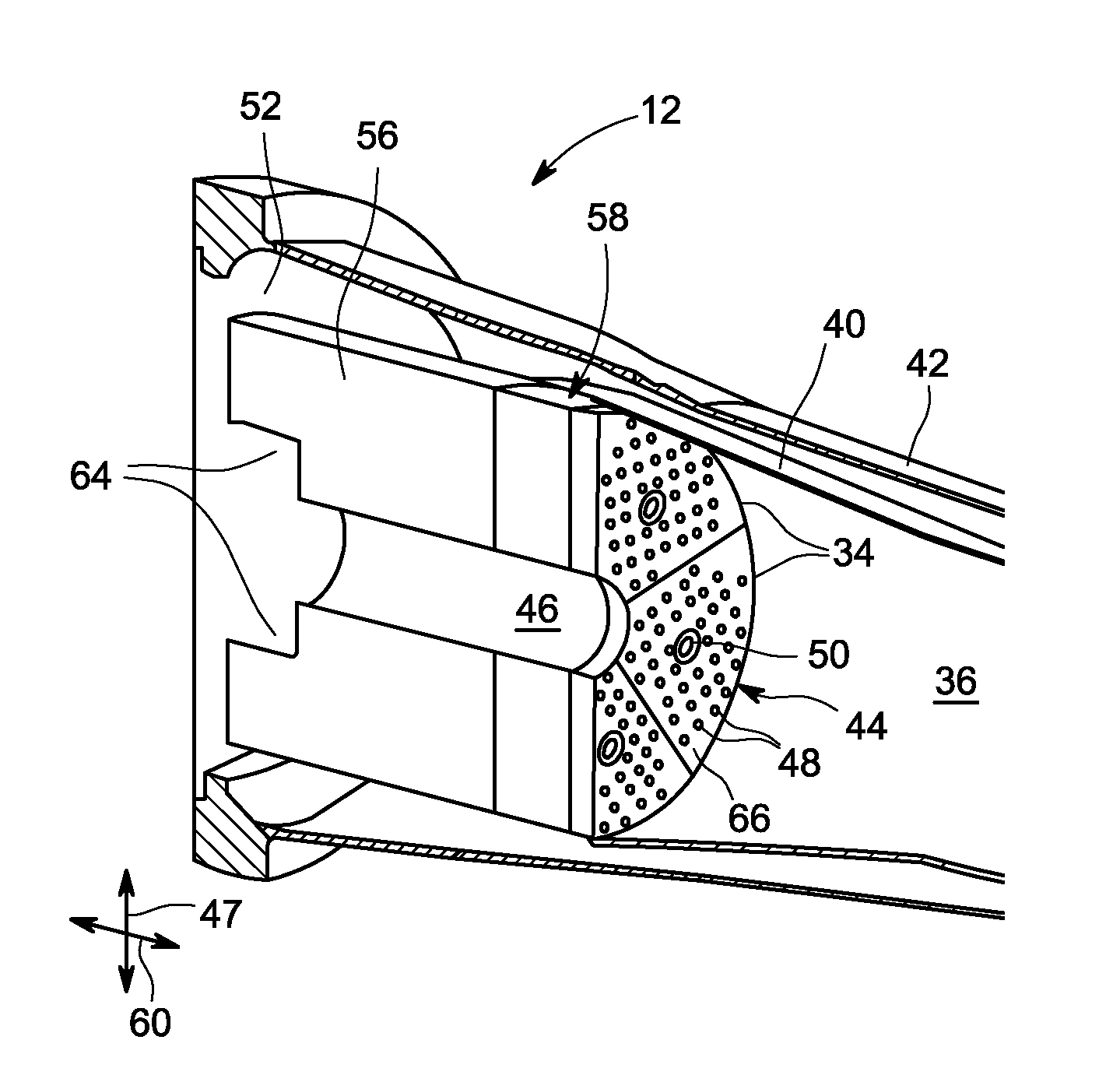
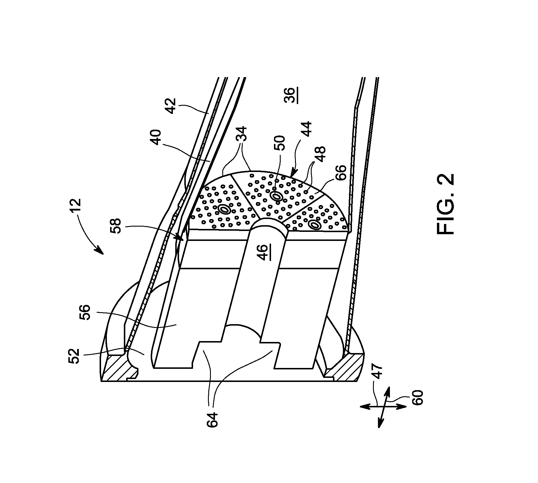
[0016]The present disclosure is directed to fuel nozzles that include multi-fuel cartridges. Each fuel nozzle may have a segmented shape, such as a wedge shaped cross section, that allows the fuel nozzle to fit together with adjacent fuel nozzles to form an annular ring of fuel nozzles within a combustor of a gas turbine. A series of mixing tubes are disposed within each fuel nozzle to produce a fuel-air mixture that is directed to the combustion zone. In particular, the mixing tubes direct air from an air plenum mixed with fuel from a fuel plenum through the mixing tubes to the nozzle face. The fuel plenum surrounds the mixing tubes and gaseous fuel from the fuel plenum is directed into the mixing tubes through apertures in the side of the tubes to produce the fuel-air mixture. The fuel nozzles also may include a multi-fuel cartridge that delivers the liquid fuel, such as fuel oil or other distillates, and the gaseous fuel, such as natural gas. Accordingly, the fuel nozzles describ...


PUM


Abstract

A combustion system uses a fuel nozzle with an inner wall having a fuel inlet in fluid communication with a fuel outlet in a fuel cartridge. The inner wall defines a mounting location for inserting the fuel cartridge. A pair of annular lip seals around the cartridge outer wall on both sides of the fuel outlet seals the fuel passage between the fuel inlet and the fuel outlet.

Description

STATEMENT OF FEDERALLY SPONSORED RESEARCH OR DEVELOPMENT[0001]This invention was made with Government support under Contract No. DE-FC26-05NT42643-DOE awarded by the Department of Energy.BACKGROUND OF THE INVENTION[0002]The subject matter disclosed herein relates to fuel delivery systems and more specifically, to fueling systems for gas turbine combustors.[0003]In general, gas turbines combust a mixture of compressed air and fuel within a combustor to produce hot combustion gases. The hot combustion gases rotate blades of the turbine to rotate a shaft that drives a load, such as an electrical generator. Mixing tubes within the combustor inject fuel and air into the combustor. In some designs, the mixing tubes pre-mix the fuel and air before the fuel and air enters the combustion zone. For example, the mixing tubes may be employed to mix a gaseous fuel with air. However, the fuel nozzles may not be designed to direct liquid fuel through the mixing tubes. A separate liquid fuel supply...

Claims


Application Information

Patent Timeline
IPC IPC(8): F02C7/22
CPCF02C7/22F23R3/286F23R3/10
Inventor BERRY, JONATHAN DWIGHT
Owner GENERAL ELECTRIC CO
Why Eureka
Try Eureka