Multi-layer coaxial cable

a coaxial cable and multi-layer technology, applied in the direction of power cables, cables, insulated conductors, etc., can solve the problems of poor workability, achieve the effect of reducing weight, simplifying the cable structure or a structure, and reducing cos

Active Publication Date: 2015-03-26
YAZAKI CORP
View PDF6 Cites 12 Cited by
  • Summary
  • Abstract
  • Description
  • Claims
  • Application Information

AI Technical Summary

Benefits of technology

[0010]The present invention has been made in consideration of the above-described circumstances, and an object of the present invention is to provide a multilayer coaxial cable which is capable of saving a space for the routing of the cable and decreasing the size of a protective member, and is capable of removing the restriction of the bending direction and improving the degree of freedom or workability.
[0048]According to the multilayer coaxial cable of the above-described (9), in addition to the effects of the above-described (1) to (8), the following effect is exhibited. That is, since another constitution is disposed in a layer shape with respect to the first high-voltage conductor that is disposed around an electrically-conducting path, it is possible to provide a small diameter to the entire multilayer coaxial cable. In addition, since the electrically-conducting path cross-sectional shape of the multilayer coaxial cable is a round shape, the cable has an ordinary shape, and thus it is possible to simplify the structure of the protective member that houses and protects the multilayer coaxial cable.

Problems solved by technology

Therefore, the workability is poor.

Method used


Image

  • Multi-layer coaxial cable
  • Multi-layer coaxial cable
  • Multi-layer coaxial cable

Examples


first embodiment

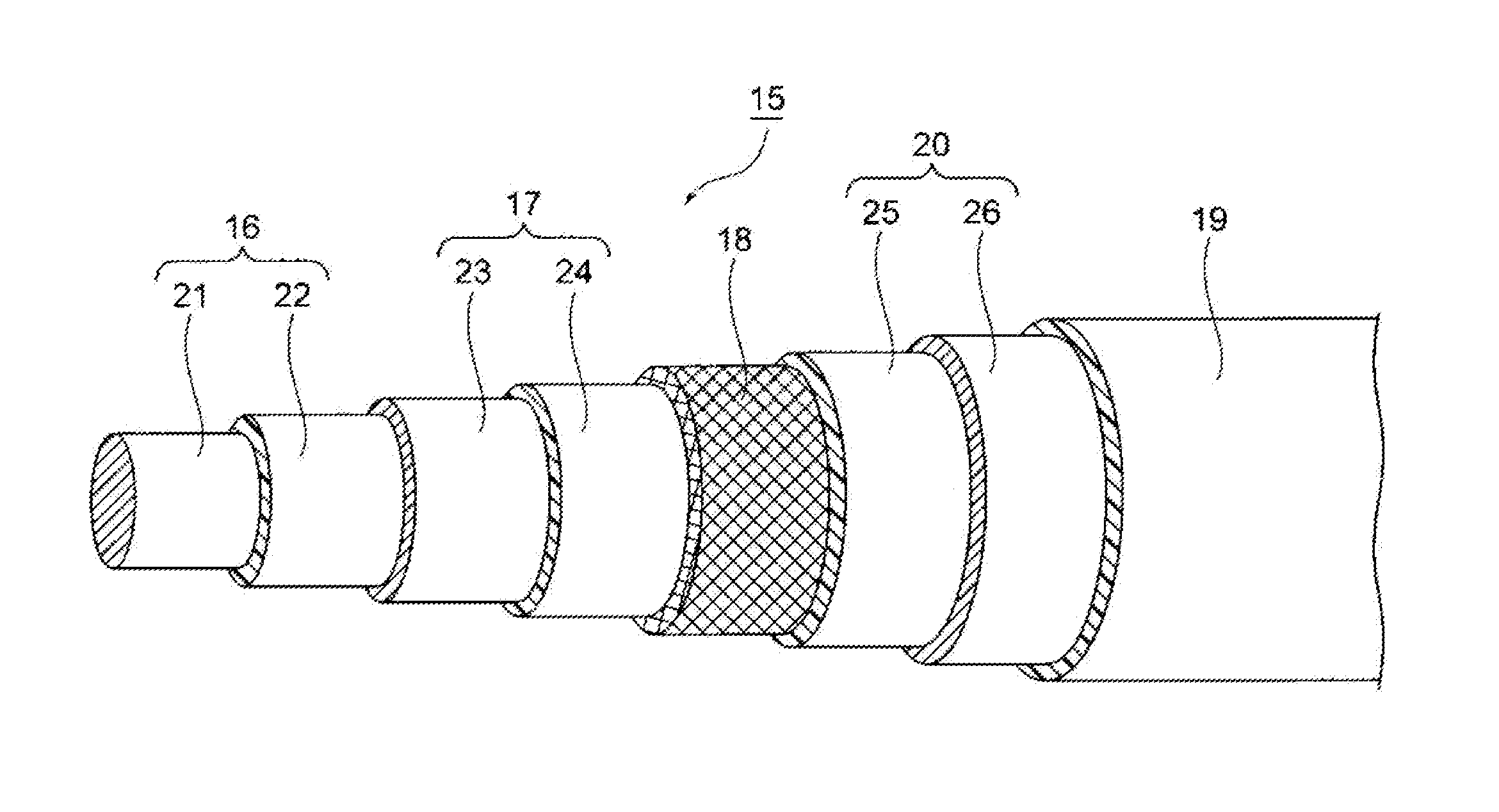
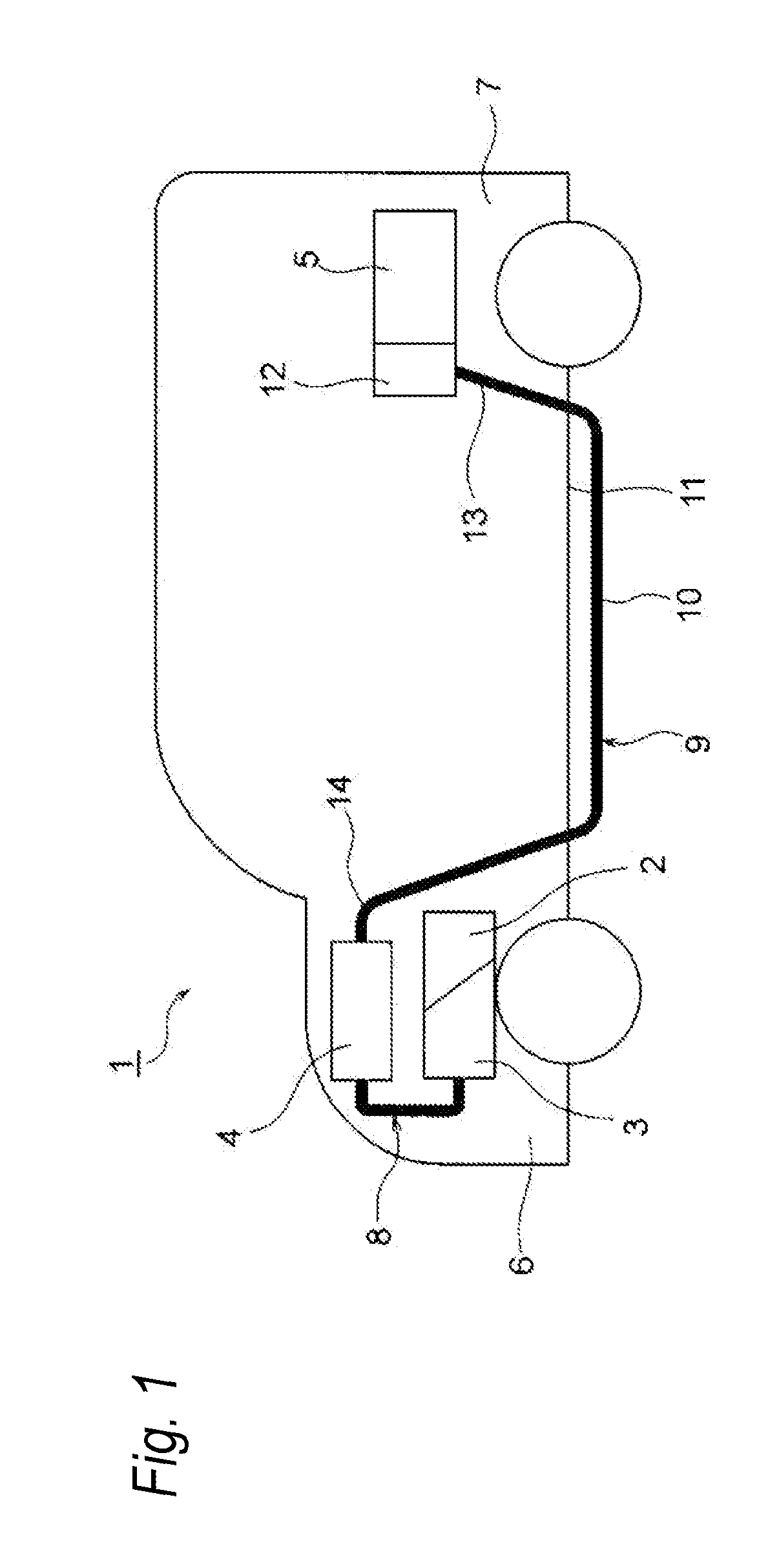
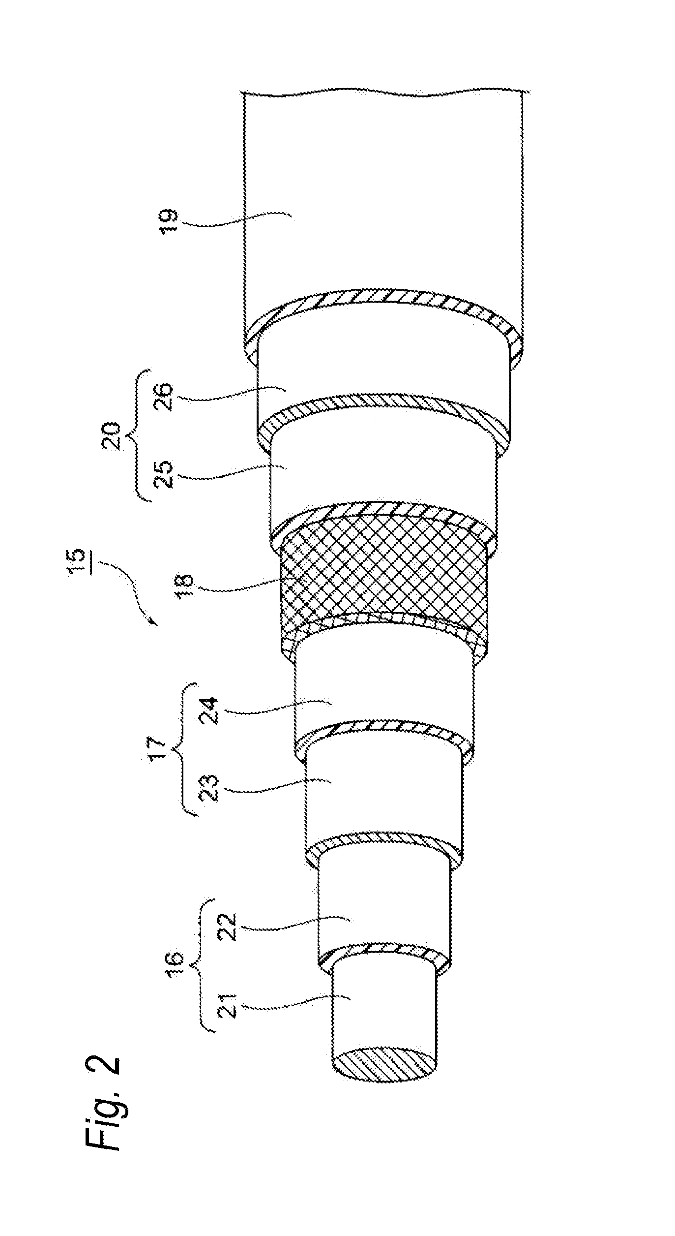
[0059]Hereinafter, a first embodiment of the multilayer coaxial cable according to the present invention will be described with reference to FIGS. 1 to 3. FIG. 1 is a schematic view illustrating the routing state of a wire harness. In addition, FIG. 2 is a perspective view illustrating the constitution of the multilayer coaxial cable of the first embodiment, and FIG. 3 is a cross-sectional view of the multilayer coaxial cable of FIG. 2.

[0060]The first embodiment will be described using an example in which a wire harness including the multilayer coaxial cable of the first embodiment is routed in a hybrid vehicle (which may be an electric vehicle or an ordinary vehicle).

[0061]In FIG. 1, Reference Sign 1 indicates a hybrid vehicle. The hybrid vehicle 1 is a vehicle driven by mixing two powers from an engine 2 and a motor unit 3. Electric power is supplied to the motor unit 3 from a battery 5 (in other words, a battery pack) through an inverter unit 4. In this example, the engine 2, the...

second embodiment

[0095]Hereinafter, a second embodiment of the multilayer coaxial cable according to the present invention will be described with reference to FIGS. 4 and 5. FIG. 4 is a perspective view illustrating the constitution of a multilayer coaxial cable of the second embodiment. In addition, FIG. 5 is a cross-sectional view of the multilayer coaxial cable of FIG. 4. Constitution members that are basically the same as in the first embodiment will be give the same reference symbols, and detailed description thereof will not be made. In addition, the multilayer coaxial cable of the second embodiment is included in a wire harness routed in the same manner as the wire harness 9 in the first embodiment illustrated in FIG. 1.

[0096]In FIGS. 4 and 5, a single string of the multilayer coaxial cable 31 includes the high-voltage positive circuit 16 and the high-voltage negative circuit 17. That is, the multilayer coaxial cable 31 includes two-system high-voltage circuits. In addition, the multilayer co...

third embodiment

[0099]Hereinafter, a third embodiment of the multilayer coaxial cable according to the present invention will be described with reference to FIGS. 6 and 7. FIG. 6 is a perspective view illustrating the constitution of a multilayer coaxial cable of the third embodiment. In addition, FIG. 7 is a cross-sectional view of the multilayer coaxial cable of FIG. 6. Constitution members that are basically the same as in the first embodiment, 2 will be give the same reference symbols, and detailed description thereof will not be made. In addition, the multilayer coaxial cable of the third embodiment is included in a wire harness routed in the same manner as the wire harness 9 in the first embodiment illustrated in FIG. 1.

[0100]In FIGS. 6 and 7, a single string of the multilayer coaxial cable 41 includes three three-phase alternate current high-voltage circuits 42. That is, in addition to the high-voltage positive circuit 16 (first high-voltage circuit) and the high-voltage negative circuit 17 ...


PUM

PropertyMeasurementUnit
voltageaaaaaaaaaa
high-voltage aaaaaaaaaa
high-voltageaaaaaaaaaa

Abstract

A multilayer coaxial cable includes high-voltage circuits that are coaxially disposed with each other. The high-voltage circuits include high-voltage conductors and high-voltage insulators that are disposed on the outside of the high-voltage conductors. In addition, the multilayer coaxial cable includes a conductive shield member that is coaxially disposed on the outside of the high-voltage circuits, and an insulating coating member that is coaxially disposed on the outside of the shield member.

Description

CROSS REFERENCE TO RELATED APPLICATIONS[0001]This application is a continuation of PCT application No. PCT / JP13 / 071,285, which was filed on Aug. 6, 2013 based on Japanese Patent Application (No. 2012 / 177738) filed on Aug. 10, 2012, the contents of which are incorporated herein by reference.BACKGROUND OF THE INVENTION[0002]1. Field of the Invention[0003]The present invention relates to a multilayer coaxial cable including a plurality of high-voltage circuits.[0004]2. Description of the Related Art[0005]FIGS. 8A to 8C are views illustrating high-voltage electrical power cables as examples of the related art. As illustrated in FIGS. 8A to 8C, in a hybrid vehicle or an electric vehicle, a battery 101 and an inverter unit 102 are electrically connected together through two high-voltage electrical power cables 103 (refer to PTL 1). The two high-voltage electric power cables 103 are cables for high-voltage use, and are respectively thick cables. Out of the two high-voltage electrical power...

Claims


Application Information

Patent Timeline
Patent Type & Authority Applications(United States)
IPC IPC(8): H01B7/02H01B1/02H01B9/02
CPCH01B7/0225H01B1/023H01B9/02H01B9/04H01B9/003
Inventor NAGAHASHI, MITSUHARU
Owner YAZAKI CORP
Why Eureka
Try Eureka