Projection display and method for projecting an overall image

Active Publication Date: 2015-03-26
FRAUNHOFER GESELLSCHAFT ZUR FOERDERUNG DER ANGEWANDTEN FORSCHUNG EV
View PDF1 Cites 41 Cited by
  • Summary
  • Abstract
  • Description
  • Claims
  • Application Information

AI Technical Summary

Benefits of technology

[0019]In embodiments of the present invention, the imager is implemented to display each of the sub-images with an image brightness which continuously decreases towards the edge of the sub-image. Thus, artifacts in an overlapping area of the projections in the image plane can be suppressed or prevented.
[0020]In embodiments of the present invention, the imager is implemented to displace all sub-images evenly in the direction of a lateral extension of the two-dimensional di

Problems solved by technology

Here, two main problems appear.
On the one hand, the comparatively large necessitated ocular focal length results in large system dimensions, which deteriorates the wearing comfort of the head-mounted display.
On the other hand, the low f-number necessitated for a large EMB together with the large FOV makes the correction of mapping errors more difficult, which increases the complexity (and hence the size and mass) of the ocular optics even further.
The main disadvantages of these known optics schemes are the resulting comparatively large system dimensions and masses as well as the complicated free form optics necessitated for aberration correction according to conventional technology, such as in (A. Takagi, S. Yamazaki, Y. Saito, and N. Taniguchi, “Development of a stereo video see-through HMD for AT systems”, in Int. Symp. On Augmented Reality, Munich, Germany, Oct. 5-6 2000), or image guide elements that are very complex to produce, such as in (Ichiro Kasai Yasushi, Yasushi Tanijiri, Takeshi Endo, Hiroaki Ueda “A Forgettable Near Eye Display”, Proc.
While this known alternative optics scheme promises a very small structural length of the optics, it allows only

Method used


Image

  • Projection display and method for projecting an overall image
  • Projection display and method for projecting an overall image
  • Projection display and method for projecting an overall image

Examples


Embodiment Construction

[0030]Before the present invention will be discussed below in more detail based on the figures, it should be noted that in the following embodiments the same elements or functionally equal elements in the figures are provided with the same reference numbers. Thus, a description of elements having the same reference numbers is mutually exchangeable and / or applicable to one another in different embodiments.

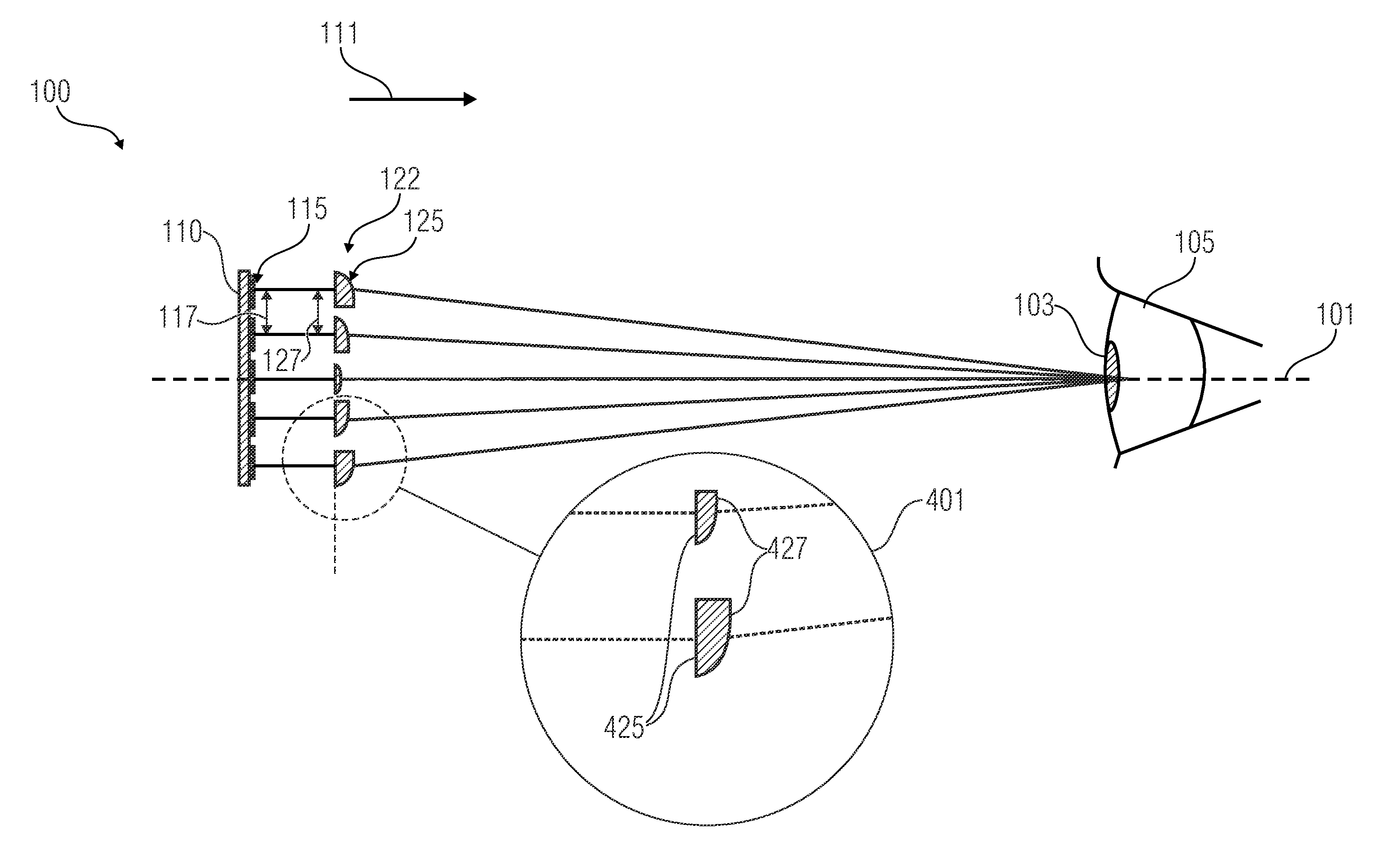
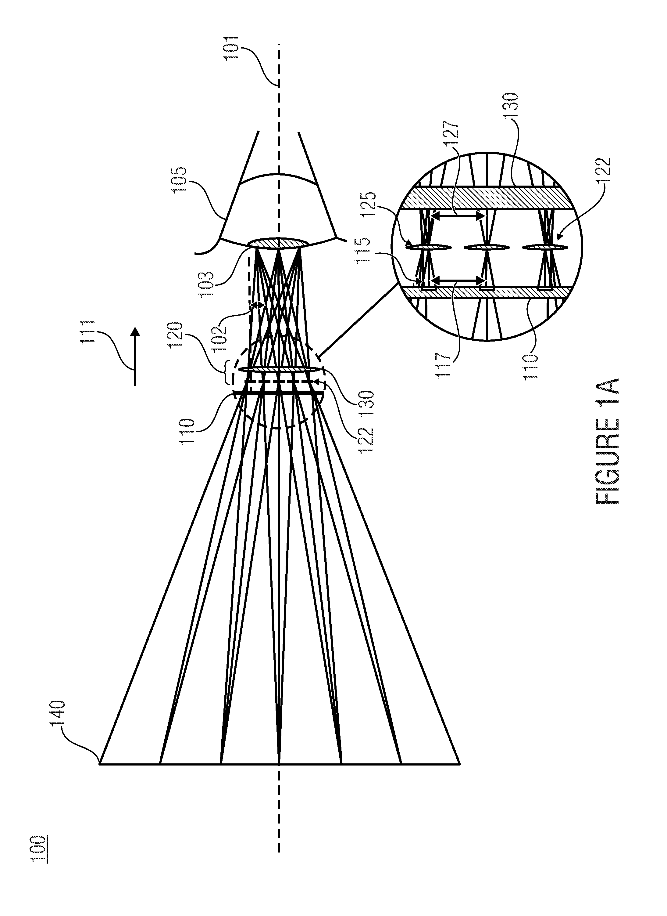
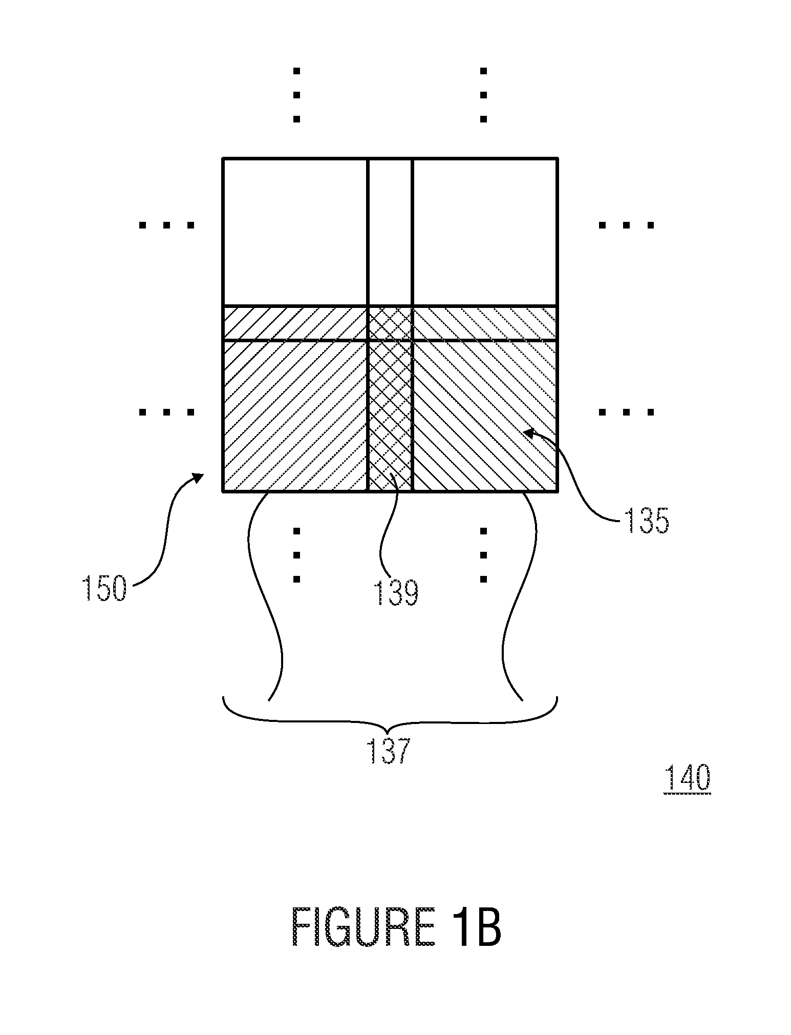
[0031]FIG. 1A shows a side view of a projection display 100 according to an embodiment of the present invention. As is shown in FIG. 1A, the projection display 100 comprises an imager 110 for displaying sub-images in a two-dimensional distribution of sub-areas 115 of the imager 110. Further, the projection display 100 shown in FIG. 1A comprises a projection optics array 120 having a two-dimensional distribution 122 of projection optics 125. FIG. 1B shows a schematic representation for illustrating an inventive mutual area overlap of projections of sub-images in an image plane. With ...


PUM


Abstract

A projection display includes an imager for displaying sub-images in a two-dimensional distribution of sub-areas of the imager and a projection optics array with a two-dimensional distribution of projection optics. The projection optics array is configured to superimpose projections of the sub-images to an overall image in an image plane such that a mutual area overlap of the projections of the sub-images in the image plane in pairs results, which is between 0.1 and 0.8 for all pairs. Here, the projection display is implemented such that the overall image is a virtual overall image.

Description

CROSS-REFERENCE TO RELATED APPLICATIONS[0001]This application is a continuation of copending International Application No. PCT / EP2013 / 056749, filed Mar. 28, 2013, which is incorporated herein by reference in its entirety, and additionally claims priority from German Application No. 10 2012 205 164.3, filed Mar. 29, 2012, which is also incorporated herein by reference in its entirety.BACKGROUND OF THE INVENTION[0002]Embodiments of the present invention relate to a projection display and a method for projecting an overall image. Further embodiments of the present invention relate to a projection display for virtual images with multichannel optics.[0003]Head-mounted displays (HMD) are commonly realized with a micro display, such as an LCD (liquid crystal display), LCoS (liquid crystal on silicon) or OLED (organic light emitting diode)-based micro display, in connection with ocular optics which maps the micro display to a distance suitable for visualization between the distinct visual d...

Claims


Application Information

Patent Timeline
IPC IPC(8): G02B27/01G03B21/14
CPCG02B27/017G03B21/14G02B2027/011G02B3/08G02B27/0101G02B27/0172G02B2027/0152G02B2027/015
Inventor SCHREIBER, PETERSIELER, MARCELKRAUS, MATTHIAS
Owner FRAUNHOFER GESELLSCHAFT ZUR FOERDERUNG DER ANGEWANDTEN FORSCHUNG EV
Why Eureka
Try Eureka