

System and method for estimating tissue heating of a target ablation zone for electrical-energy based therapies
a tissue heating and electrical energy technology, applied in the field of medical therapies, can solve the problems of difficult or sometimes impossible to place electrodes in the correct location of the tissue, difficult to predict whether the selected locations will ablate the entire treatment target area, and modest two-dimensional treatment regions may take at least 30 minutes to several hours to compl
- Summary
- Abstract
- Description
- Claims
- Application Information
AI Technical Summary
Benefits of technology
Problems solved by technology
Method used
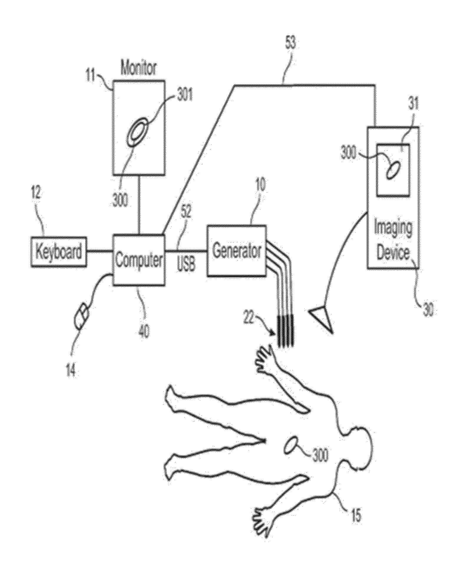
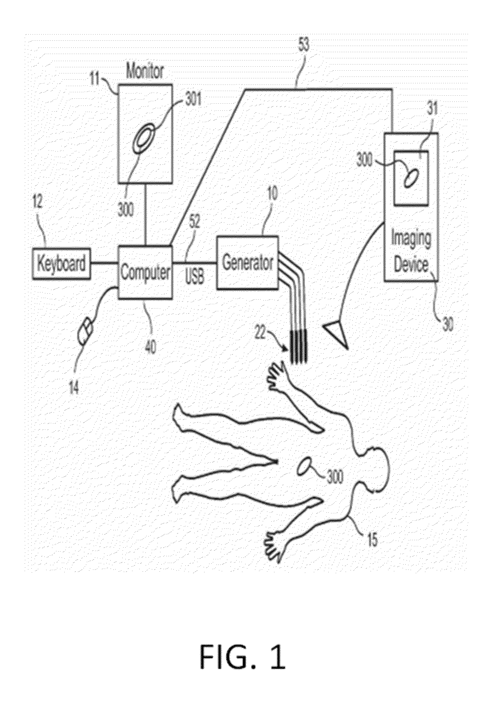
Image

Examples
example 1
Materials And Methods
[0169]The tissue was modeled as a 10-cm diameter spherical domain using a finite element package (Comsol 4.2a, Stockholm, Sweden). Electrodes were modeled as two 1.0-mm diameter blunt tip needles with exposure lengths (Y) and edge-to-edge separation distances (X) given in Table 1. The electrode domains were subtracted from the tissue domain, effectively modeling the electrodes as boundary conditions.
TABLE 1Electrode configuration and relevantelectroporation-based treatment values used in study.PARAMETER VALUESMEANW [V / cm]500, 1000, 1500, 2000,17502500, 3000X [cm]0.5, 1.0, 1.5, 2.0, 2.51.5Y [cm]0.5, 1.0, 1.5, 2.0, 2.5, 3.01.75Z [cm]1.0, 1.25, 1.5, 2.0, 3.0, 4.0,2.9685.0, 6.075
[0170]The electric field distribution associated with the applied pulse is given by solving the Laplace equation:
∇·(σ(|E|)∇φ)=0 (1)
[0171]where σ is the electrical conductivity of the tissue, E is the electric field in V / cm, and φ is the electrical potential (Edd and Davalos, 2007). Boundari...
example 2
Determining the Relationship Between Blunt Tip Electrode Configuration and Resulting Current after IRE Treatment
[0180]Model Assumptions:
[0181]Gompertz Conductivity: Pulse duration=50 μs, Ex-vivo kidney tissue
[0182]Baseline Conductivity: σ=0.1 S / m
[0183]Spherical Domain: diameter=10 cm
[0184]Applied Voltage: Voltage=1000 V
[0185]Parametric Study:
[0186]Total Combinations: 720 models
[0187]Maximum Conductivity: 1.0×, 1.25×, 1.5×, 2×, 3×, 4×, 5×, 6× the baseline
[0188]Edge-to-edge Distance: 5, 10, 15, 20, 25 mm
[0189]Electrode Exposure: 5, 10, 15, 20, 25, 30 mm
[0190]Electrode Radius: 0.5, 0.75, 1.0 mm
[0191]The output of statistical analysis software (JMP 9.0) used to fit model and determine the coefficients for all parameter combinations is shown in the tables of FIGS. 8A and 8B and the plot of FIG. 8C.
[0192]Parameters of Best Fit for Dynamic Conductivity Changes Between 1×-6× the Baseline Conductivity (R2=0.96):
[0193]a=−1.428057; (*Intercept Estimate*)
[0194]b=−0.168944; (*Gap Estimate*)
[0195...
example 3
[0227]Comparison of analytical solutions with statistical (numerical) model to calculate current and explanation of procedure that results in 3D IRE volume.
[0228]The process of backing-out the electrical conductivity using the analytical solutions and the one proposed in the “Towards a Predictive Model of Electroporation-Based Therapies using Pre-Pulse Electrical Measurements” abstract presented in the IEEE Engineering in Medicine and Biology Conference in Aug. 28, 2012 in San Diego, Calif. were compared. A method to determine the predictive power of the equations to calculate current is analyzing the residuals of the 1440 combinations of parameters examined. In the context of this specification, a residual is the difference between the predicted current and the actual current. As can be seen in FIGS. 11A and 11B with increasing non-linear change in conductivity due to electroporation and increasing applied electric field there is an increase in the residual for both cases. The main...
PUM
 Abstract
Description
Claims
Application Information