Organic-inorganic hybrid light emitting device, method for manufacturing the same, and organic-inorganic hybrid solar cell

a technology of organic inorganic and solar cells, which is applied in the direction of solid-state devices, semiconductor devices, thermoelectric devices, etc., can solve the problems of limited application of organic electroluminescent displays, light-emitting devices, and agglomeration of fluorescent particles, so as to improve the power efficiency of organic light-emitting devices and improve the luminance efficiency of them. , the effect of brighter ligh

Inactive Publication Date: 2015-04-02
UNIV OF SEOUL IND COOP FOUND
View PDF3 Cites 8 Cited by
  • Summary
  • Abstract
  • Description
  • Claims
  • Application Information

AI Technical Summary

Benefits of technology

[0021]The organic-inorganic composite light-emitting device configured as above is advantageous in that an inorganic thin film layer is inserted and formed between organic luminescent layers, and thus the injection of electrons that occurs when low voltage is applied stabilizes the structure of the organic luminescent layer, thereby emitting brighter light.
[0022]Further, the organic-inorganic composite light-emitting device is effective in greatly improving the power efficiency of an organic light-emitting device by greatly increasing the luminance efficiency thereof.
[0023]Moreover, the organic-inorganic composite light-emitting device can exhibit improved luminance efficiency at low cost because it can be manufactured by directly using a conventional organic light-emitting device structure and a conventional process of manufacturing an organic light-emitting device.
[0024]Meanwhile, the organic-inorganic composite solar cell configured as above is effective in greatly improving the efficiency of an organic solar cell by inserting and forming an inorganic thin film layer between organic photoactive layers.

Problems solved by technology

However, to date, the application of the organic electroluminescent display has been restricted due to the limitation in performance of an organic light-emitting device, and thus efforts to improve the performance of the organic light-emitting device have continuously been made.
However, this hybrid light-emitting device is disadvantageous in that fluorescent particles agglomerate in the process of applying the fluorescent nanomaterial layer using spin coating.
However, the organic-inorganic hybrid electroluminescent device manufactured by this method is not a genuine organic-inorganic composite light-emitting device, and is disadvantageous in that conventional manufacturing processes and equipment cannot be used.

Method used


Image

  • Organic-inorganic hybrid light emitting device, method for manufacturing the same, and organic-inorganic hybrid solar cell
  • Organic-inorganic hybrid light emitting device, method for manufacturing the same, and organic-inorganic hybrid solar cell
  • Organic-inorganic hybrid light emitting device, method for manufacturing the same, and organic-inorganic hybrid solar cell

Examples


Embodiment Construction

[0037]Hereinafter, preferred embodiments of the present invention will be described in detail with reference to the attached drawings.

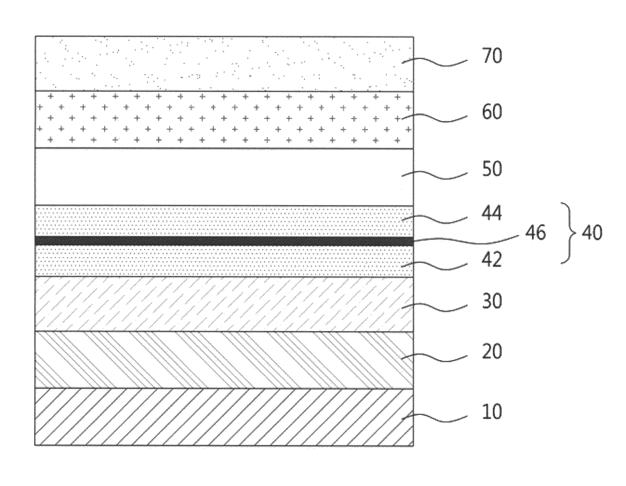
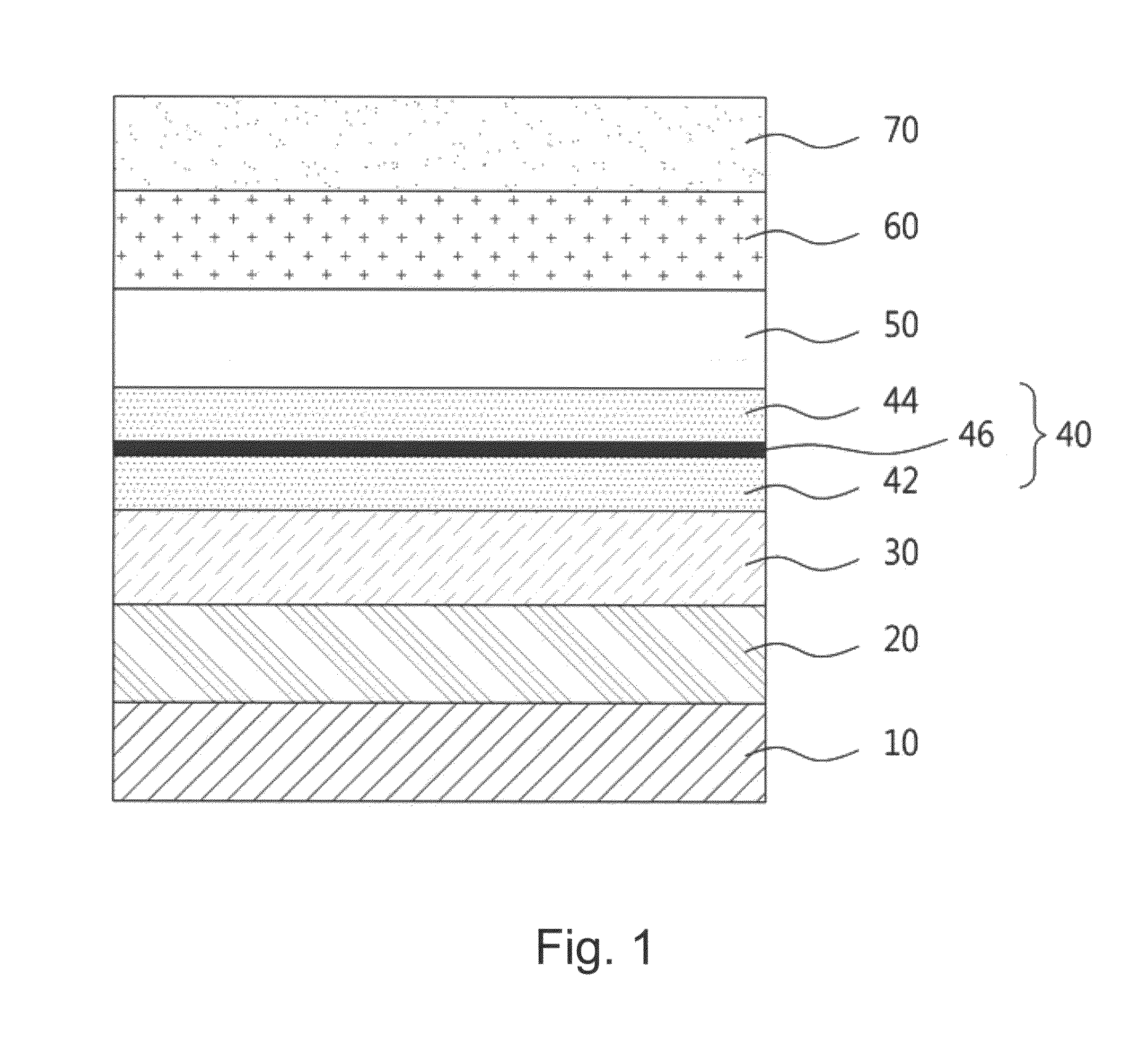
[0038]FIG. 1 is a schematic sectional view showing the laminate structure of an organic-inorganic composite light-emitting device according to an embodiment of the present invention.

[0039]The organic-inorganic composite light-emitting device according to an embodiment of the present invention includes a luminescent layer 40 disposed between a first electrode 10 and a second electrode 70 facing each other.

[0040]The organic-inorganic composite light-emitting device further includes: a hole injection layer 20 being in contact with the first electrode 10 to receive holes from the first electrode 10; and a hole transport layer 30, one side of which is in contact with the hole injection layer 20 and the other side of which is in contact with the luminescent layer 40, to transport the holes charged in the hole injection layer 20 to the luminescent layer 40, ...


PUM


Abstract

The present invention provides an organic-inorganic composite light-emitting device including a luminescent layer emitting high-brightness light using low voltage, wherein the luminescent layer has a sandwich structure in which organic luminescent layers are formed on both sides of an inorganic thin film layer.The organic-inorganic composite light-emitting device configured as above is advantageous in that an inorganic thin film layer is inserted and formed between organic luminescent layers, and thus the injection of electrons that occurs when low voltage is applied stabilizes the structure of the luminescent layer, thereby emitting brighter light. Further, the organic-inorganic composite light-emitting device is effective in greatly improving the power efficiency of an organic light-emitting device by greatly increasing the luminance efficiency thereof. Moreover, the organic-inorganic composite light-emitting device can exhibit improved luminance efficiency at low cost because it can be manufactured by directly using a conventional organic light-emitting device structure and a conventional process of manufacturing an organic light-emitting device.

Description

TECHNICAL FIELD[0001]The present invention relates to a light-emitting device, and, more particularly, to a light-emitting device including a luminescent layer made of a laminate of an organic material and an inorganic material, and a manufacturing method thereof.BACKGROUND ART[0002]Recently, with the advent of the information age, display technologies for visually expressing electrical information signals have been rapidly advanced. Accordingly, various flat-panel displays have been developed to rapidly replace conventional cathode ray tubes (CRTs).[0003]Specific examples of such flat-panel displays may include liquid crystal displays (LCDs), organic light-emitting displays (OLEDs), electrophoretic displays (EPDs), electric paper displays, plasma display panels (PDPs), field emission displays (FEDs), electroluminescent displays (ELDs), and electro-wetting displays (EWDs).[0004]Such flat-panel displays commonly include a flat display panel for realizing an image as an essential elem...

Claims


Application Information

Patent Timeline
Patent Type & Authority Applications(United States)
IPC IPC(8): H01L51/50H01L51/56H01L51/42
CPCH01L51/5012H01L51/56H01L51/4213Y02E10/549H10K30/353H10K50/11H10K50/125H10K50/14H10K50/805H10K71/00
Inventor HONG, WAN-SHICKSONG, TAE-HO
Owner UNIV OF SEOUL IND COOP FOUND
Why Eureka
Try Eureka