Ion source

a technology of ion source and inside wall surface, which is applied in the direction of ion implantation coating, discharge tube ion gun, coating, etc., can solve the problem of limited method us

Inactive Publication Date: 2015-04-02
INST OF GEOLOGICAL & NUCLEAR SCI
View PDF11 Cites 21 Cited by
  • Summary
  • Abstract
  • Description
  • Claims
  • Application Information

AI Technical Summary

Benefits of technology

[0042]The qualifiers “upper”, “lower”, “top”, “bottom”, “underside”, “topside”, “above”, and “below”, and the like, and “horizontal” and “vertical”, and the like, when used herein with reference to features as shown in the accompanying figures are for convenience and clarity of explanation, and are not to be construed as limiting the ion source, and / or its components, or the operation or use of the ion source, and / or its components, to any particular orientation, including, but not limited to, any orientation described herein and / or depicted in the accompanying figures.

Problems solved by technology

These methods are limited in their use because of the complexity of the technology and adhesion problems at the interface between the coating layer and the underlying wall material.

Method used


Image

  • Ion source
  • Ion source
  • Ion source

Examples


Embodiment Construction

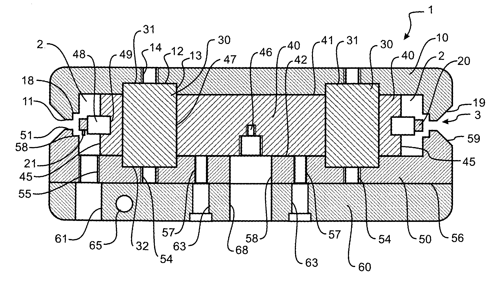
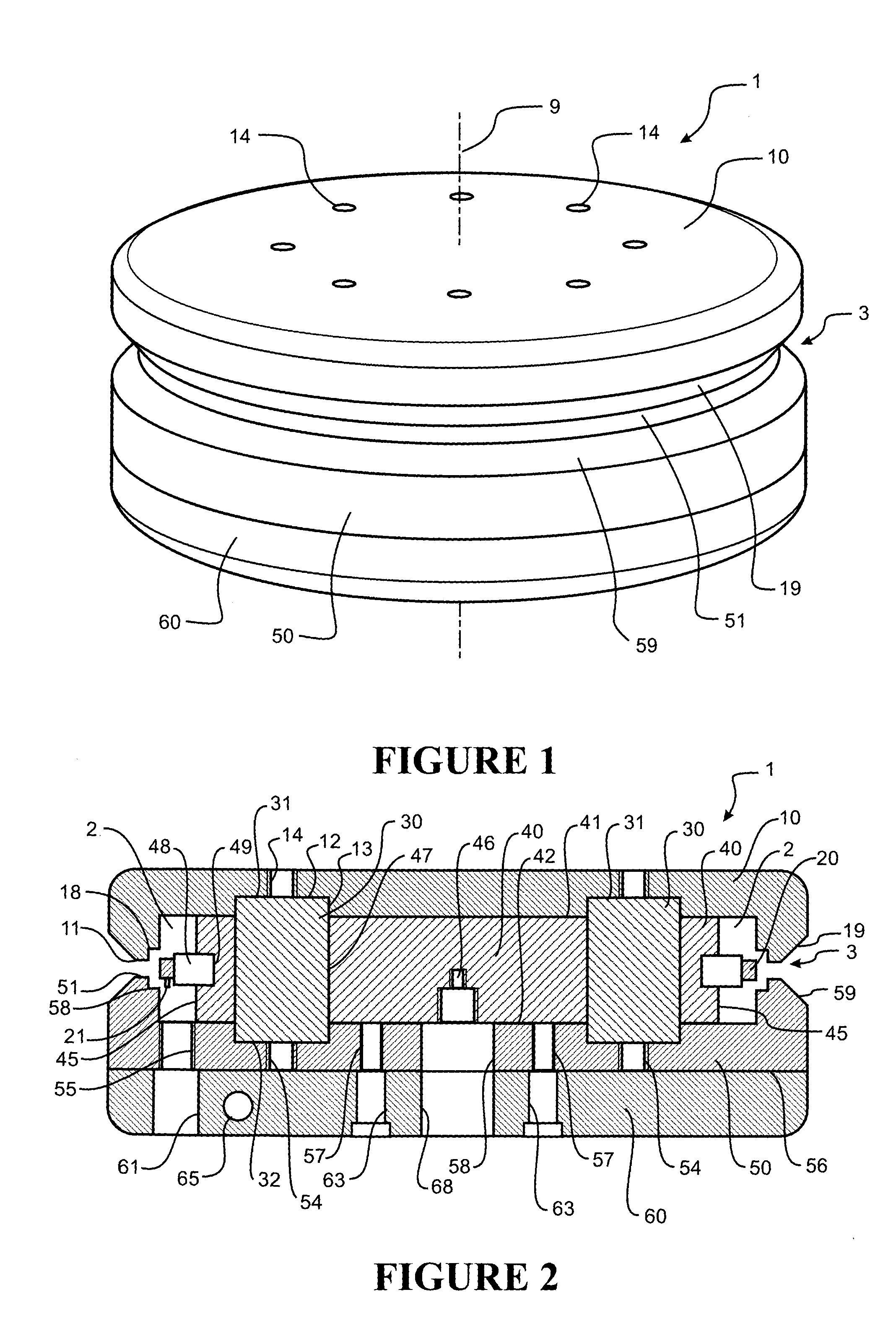
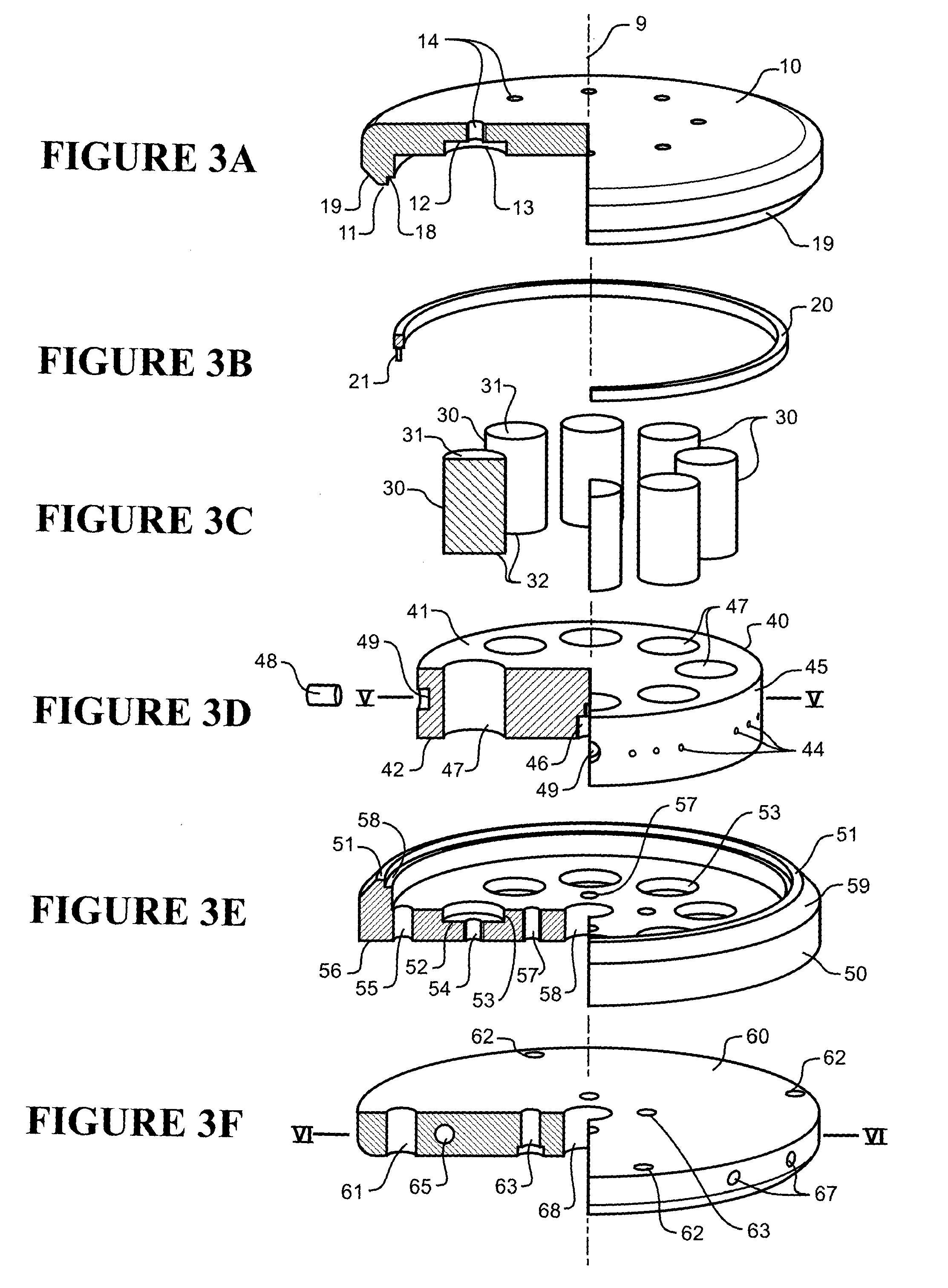
[0057]An ion source 1 according to the invention is shown in the isometric view of FIG. 1, the cross-sectional view of FIG. 2, and by the exploded view of the major components in FIGS. 3A to 3F, when taken together.

[0058]The major components of the ion source are each generally circular and share a common axial centreline 9. The major components of the ion source are, in the order shown in FIGS. 3A to 3F:[0059]a first cathode pole piece 10,[0060]a anode 20,[0061]a circular array of permanent rare earth magnets 30,[0062]a gas manifold 40,[0063]a second cathode pole piece 50, and[0064]a coolant jacket 60.

[0065]The two cathode pole pieces are made from soft or mild steel and are spaced apart from one another to form a cavity 2 therebetween. A circular edge 11 of the first cathode pole piece 10 is spaced apart from a circular edge 51 of the second cathode pole piece 50 to define a circular cathode gap 3 between the respective edges of the pole pieces. A rabbet 18, 58 at the radially inn...


PUM

PropertyMeasurementUnit
depthaaaaaaaaaa
operating temperaturesaaaaaaaaaa
Curie temperatureaaaaaaaaaa

Abstract

The invention provides an ion source comprising first and second cathode pole pieces spaced apart from one another to form a cavity therebetween, an edge of the first cathode pole piece being spaced apart from an edge of the second cathode pole piece to define an elongate cathode gap between the respective edges of the pole pieces, the elongate cathode gap having a longitudinal axis; at least one magnet arranged for magnetising the first and second cathode pole pieces with opposite magnetic polarities; an elongate anode located in the cavity, the anode being spaced apart from the first and second cathode pole pieces and having a longitudinal axis, the longitudinal axis of the elongate anode and the longitudinal axis of the elongate cathode gap substantially coplanar; a first electrical connection which extends from outside the cavity to the anode; and a gas feed conduit which extends from outside the cavity to inside the cavity for introducing a gas into the cavity.

Description

FIELD OF INVENTION[0001]The present invention relates to methods and devices for the treatment of the inside wall surface of pipes and tubes. More particularly, but not exclusively, it relates to the chemical and physical modification of the surface of inner and / or outer pipe walls with high current ion beams from plasma ion sources. The invention also relates to methods and devices for producing new chemical and physical properties of pipes with ion implantation under backing pressure vacuum conditions.BACKGROUND TO THE INVENTION[0002]Developments in pipeline modifications are sought to improve the lifetime of the inner walls. Incorporation of ‘alien’ atoms in metal and plastic surfaces improves the chemical and physical resistance of the pipes in industrial processes, such as geothermal pipelines and stainless steel pipelines in the food processing industries.[0003]Methods have been developed to coat inner wall tubes of small diameter with chemical vapour deposition and anodic tre...

Claims


Application Information

Patent Timeline
Patent Type & Authority Applications(United States)
IPC IPC(8): H01J37/08H01J37/317
CPCH01J37/08H01J2237/002H01J37/3171C23C14/046C23C14/48C23C14/562H01J3/04H01J27/14H01J2237/061
Inventor FUTTER, RICHARD JOHNMARKWITZ, ANDREAS
Owner INST OF GEOLOGICAL & NUCLEAR SCI
Why Eureka
Try Eureka