Optical measurement apparatus

Active Publication Date: 2015-04-02
HITACHI-LG DATA STORAGE
View PDF5 Cites 6 Cited by
  • Summary
  • Abstract
  • Description
  • Claims
  • Application Information

AI Technical Summary

Benefits of technology

[0023]According to the present invention, an optical measurement apparatus can be provided that can suppress influence of a reflected beam from the surface of a target to be measured or from a

Problems solved by technology

In the OCT, a light beam from a light source is split into two: a signal beam to irradiate a target to be measured, and a reference beam to be reflected by a reference beam mirror without irradiating the

Method used


Image

  • Optical measurement apparatus
  • Optical measurement apparatus
  • Optical measurement apparatus

Examples


embodiment 1

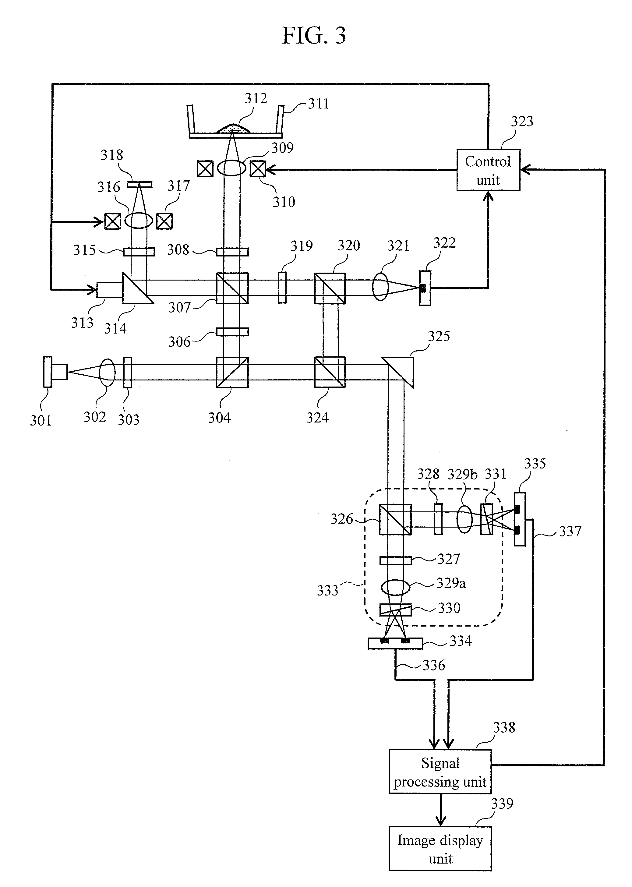
[0036]FIG. 3 is a schematic view showing the basic embodiment of the optical measurement apparatus of the present invention.

[0037]A laser beam is emitted from a light source 301. The laser beam is converted into a collimated beam by a collimator lens 302, and is subjected to polarization rotation by a λ / 2 plate 303 capable of adjusting the optical axis direction, and is further split into two by a polarization beam splitter 304. One of the light beams split by the polarization beam splitter 304 becomes incident on a polarization beam splitter 324 as a reference beam. The other of the light beams split by the polarization beam splitter 304 is subjected to polarization rotation by a λ / 2 plate 306 capable of adjusting the optical axis direction, and is then split into two: a signal beam and a control beam by a polarization beam splitter 307.

[0038]The signal beam passes through a λ / 4 plate 308 at which the optical axis is set to about 22.5° with respect to the horizontal direction, and ...

embodiment 2

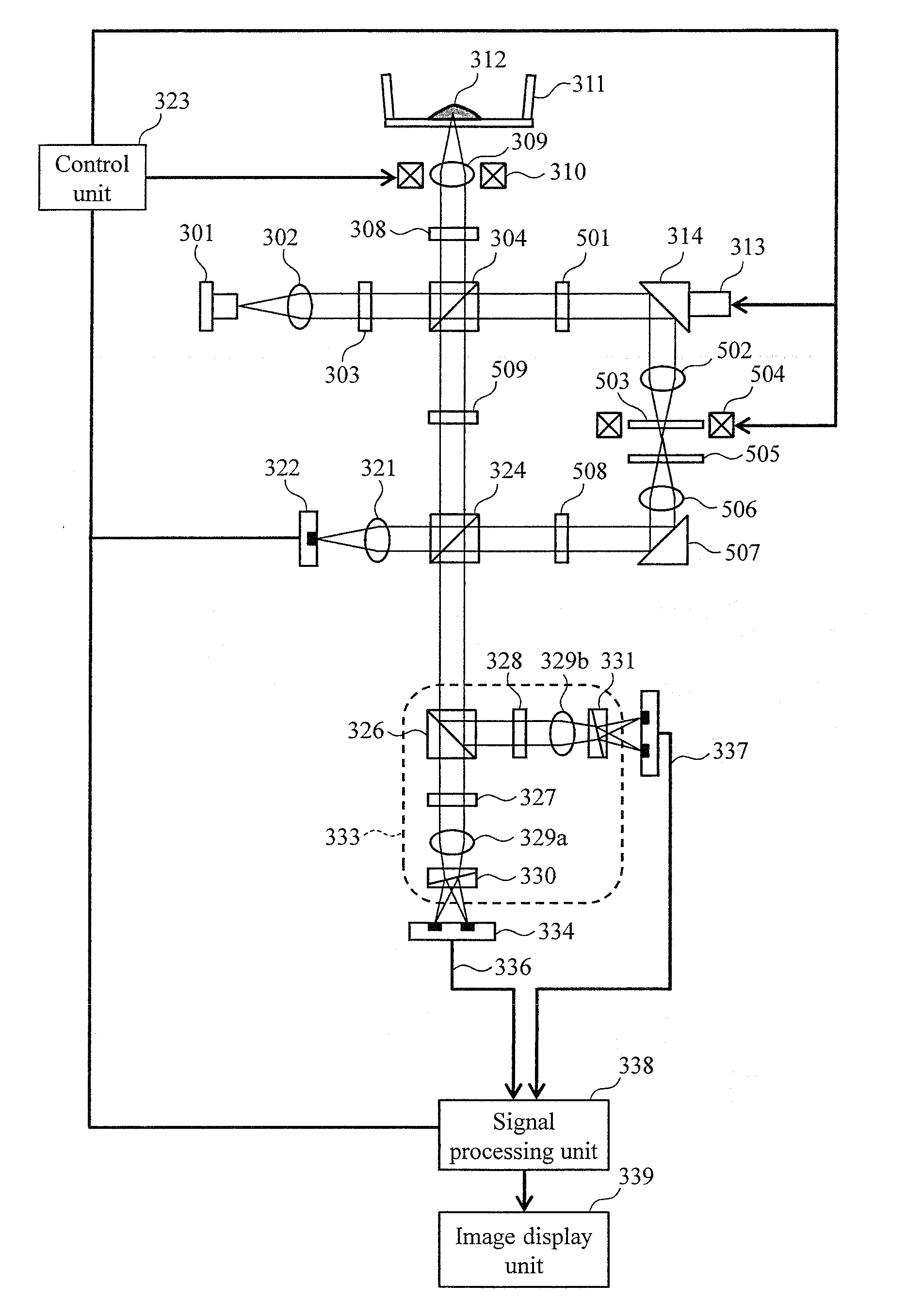
[0075]FIG. 6 is a schematic view showing another embodiment of the optical measurement apparatus of the present invention. It should be noted that component parts that are identical to those shown in FIG. 3 are denoted by identical reference numerals, and detailed description thereof will be omitted. This embodiment differs from the first embodiment in the method of generating a control beam and the method of adjusting defocus of the control beam.

[0076]A laser beam is emitted from the light source 301. The laser beam is converted into a collimated beam by a collimator lens 302, and is subjected to polarization rotation by a λ / 2 plate 303 capable of adjusting the optical axis direction, and is further split into two by a polarization beam splitter 304. One of the light beams split by the polarization beam splitter 304 passes through a λ / 4 plate 308 at which the optical axis is set to about 22.5° with respect to the horizontal direction, as a signal beam, and thus is converted from th...

embodiment 3

[0084]FIG. 7 is a schematic view showing another embodiment of an optical measurement apparatus in accordance with the present invention. It should be noted that component parts that are identical to those shown in FIG. 3 are denoted by identical reference numerals, and detailed description thereof will be omitted. This embodiment differs from Embodiment 2 in that two interference beams are generated by interference optics, and a piezoelectric element for rapidly modulating the phase of a reference beam is used.

[0085]This embodiment is substantially similar to Embodiment 2 up to a configuration in which a laser beam is emitted from a light source 301 and a controlled signal beam is combined with a reference beam to generate a combined beam. However, this embodiment differs from Embodiment 2 in that a mirror 507 is mounted on a piezoelectric element 601 for rapidly modulating the phase of the reference beam. The combined beam is guided to interference optics 602 that include a λ / 2 pl...


PUM


Abstract

A clear image of a target to be measured is obtained by suppressing influence of a reflected beam from the surface of the target or a measurement target holding unit. A laser beam emitted from a light source is split into a signal beam, reference beam, and control beam. The signal beam is focused onto the target with an objective lens, so the target is irradiated with the signal beam. The amount of defocus of the control beam is controlled with a defocus control unit, and the phase of the control beam is controlled with a phase control unit. A signal beam reflected or scattered by the target is combined with the control beam to generate a controlled signal beam, and the controlled signal beam is combined with the reference beam. A plurality of interference beams with different phases are generated with interference optics, and phase diversity detection is performed.

Description

CLAIM OF PRIORITY[0001]The present application claims priority from Japanese patent application JP 2013-206962 filed on Oct. 2, 2013, the content of which is hereby incorporated by reference into this application.TECHNICAL FIELD[0002]The present invention relates to an optical measurement apparatus, and more particularly to an optical measurement apparatus for optically observing cross-sections.RELATED ART[0003]In recent years, optical coherence tomography (OCT) has been drawing attention that acquires an image reflecting the surface structure or the inner structure of a target to be measured, using a light beam (See Patent Document 1). As the OCT is not invasive on the human body, it is expected to be applied to the medical field and the biological field, in particular. In the ophthalmological field, apparatuses for forming images of fundus oculi or corneas have been put into practical use. In the OCT, a light beam from a light source is split into two: a signal beam to irradiate a...

Claims


Application Information

Patent Timeline
IPC IPC(8): G01B9/02
CPCG01B9/02075G01B9/02091G01B9/02027A61B5/0066G01B9/02025G01B9/02059G01B9/02081G01B2290/70
Inventor OSAWA, KENTARO
Owner HITACHI-LG DATA STORAGE
Why Eureka
Try Eureka