Radiation image processing apparatus and method

a radiation image and processing apparatus technology, applied in the field of radiation image processing apparatus and method, can solve the problems of increased imaging system cost, unable to achieve radiation image having a desired image quality, and unable to perform imaging with desired application conditions

Active Publication Date: 2015-04-02
FUJIFILM CORP
View PDF20 Cites 26 Cited by
  • Summary
  • Abstract
  • Description
  • Claims
  • Application Information

AI Technical Summary

Benefits of technology

[0073]According to the present invention, imaged contrast information representing a contrast of a radiation image is obtained, an intended application condition of radiation is set, and target contrast information representing an intended contrast of the radiation image is obtained base on the intended application condition. Then, a contrast correction amou...

Problems solved by technology

In the meantime, adoption of an arrangement in which a plurality of materials, as the target and the filter, is switchable may pose a problem that the cost of the imaging system is increased.
On the other hand, if the target and the filter cannot be selectable, the radiographer may not perform imaging with desired application conditions and a radiation image having a desired image quality may not be obtained.
Still further, there may be a case in which desired application conditions cannot be set due to imaging constraints.
Portable imaging performed, for example, in a patient room, however, the tube voltage may be set only to about 80 kV due to imaging constraints.
In such a case also, a radiation image having a desired image quality may not be obtained.
Therefore, the consideration of only the application con...

Method used


Image

  • Radiation image processing apparatus and method
  • Radiation image processing apparatus and method
  • Radiation image processing apparatus and method

Examples


first embodiment

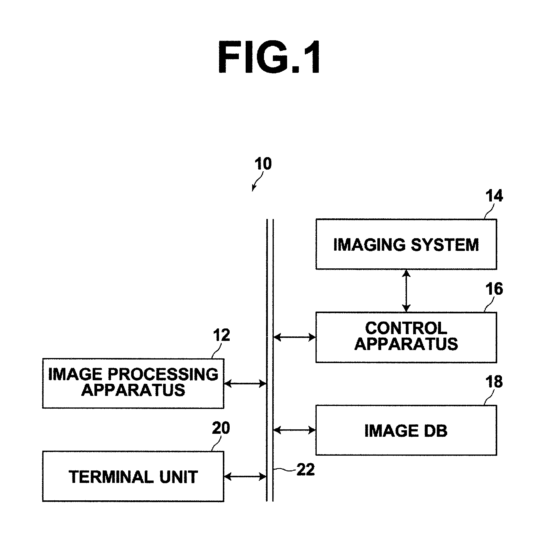
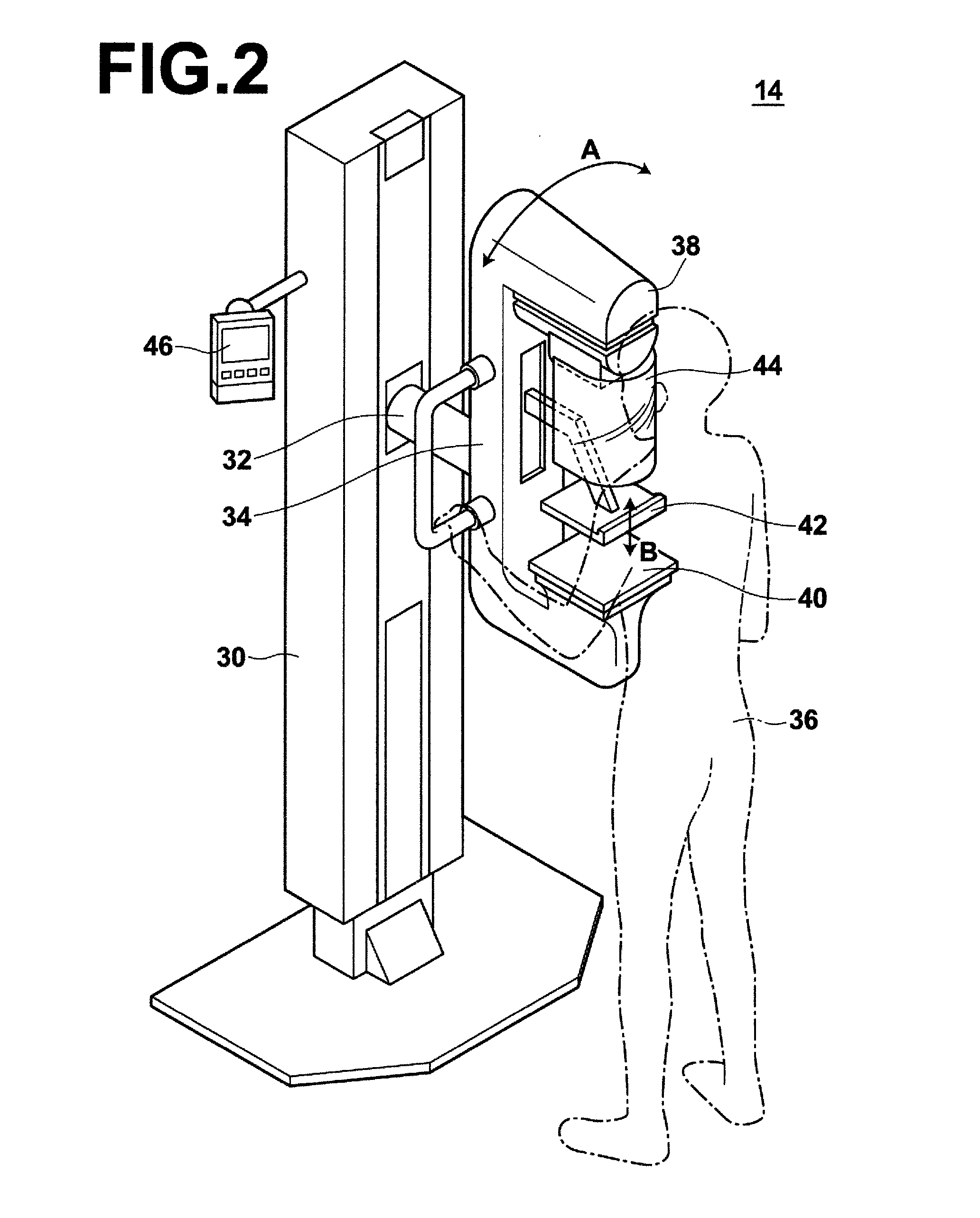
[0106]FIG. 4 is a block diagram of control circuits of the image processing apparatus, a mammography imaging system, and a control apparatus according to the The control apparatus 16 that controls the mammography imaging system 14 includes a source drive control unit 70 that drive controls the X-ray source 50 according to the given application conditions, a compression paddle drive control unit 72 that drive controls the compression paddle 42 and compresses a breast M of the subject 36 against the imaging platform 40, and a detector control unit 76 that controls a solid-state detector 74 accommodated in the imaging platform 40 to obtain a radiation image.

[0107]The image processing apparatus 12 includes a thickness calculation unit 78 that calculates a thickness of the breast M based on the position information of the compression paddle 42 supplied from the compression paddle drive control unit 72, an application condition setting unit 80 that sets application conditions to be set t...

second embodiment

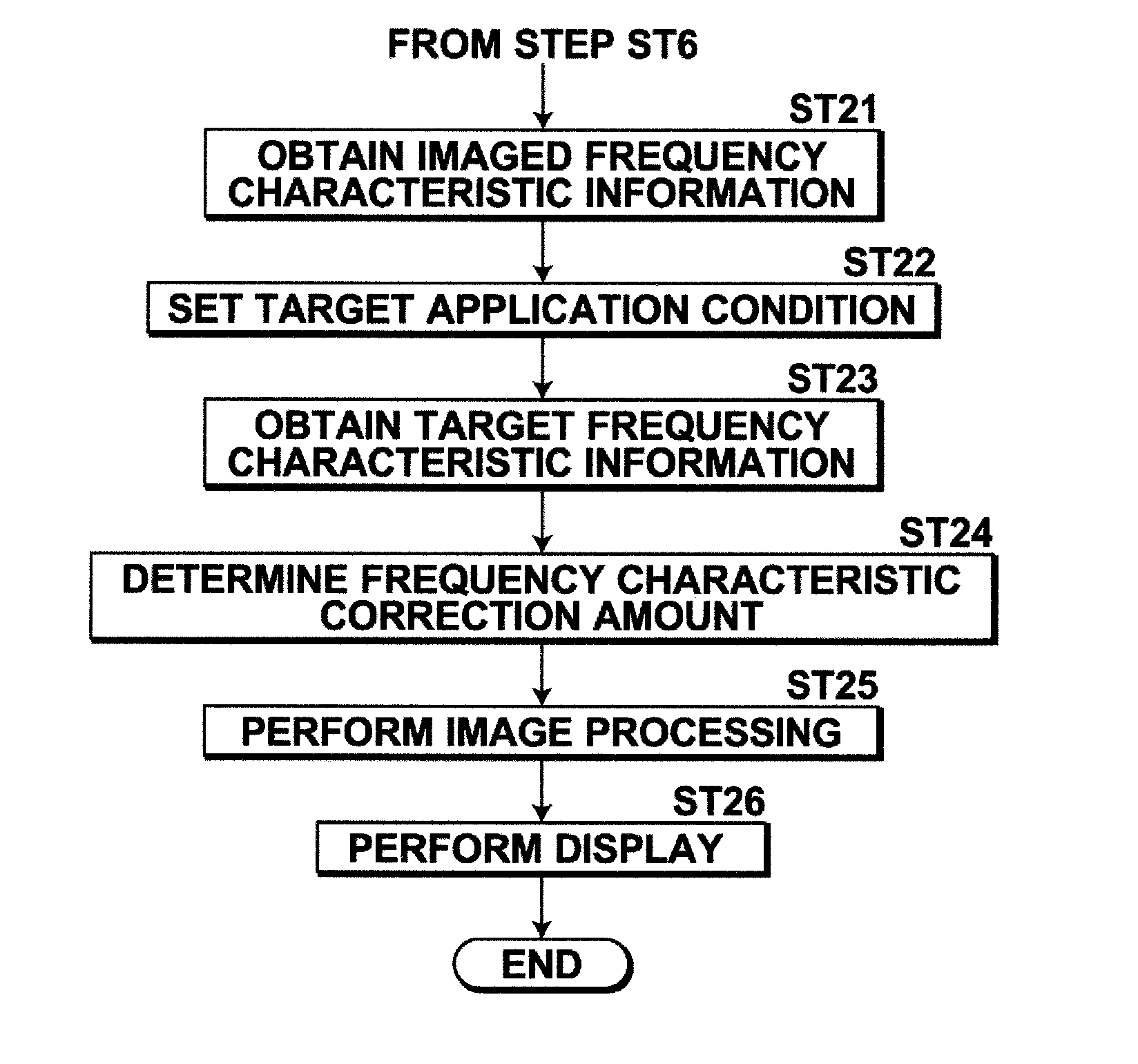
[0129]In the second embodiment, the storage unit 110 stores Frequency Characteristic Table T3 that defines frequency characteristic information. Frequency Characteristic Table T3 is a three-dimensional table that defines frequency characteristics corresponding to a plurality of breast thicknesses, a plurality of tube voltages, and a plurality of mammary gland / fat ratios with respect to each combination of target and filter. The frequency characteristic as used in the present embodiment represents a response value at a frequency of 2 cycles / mm which is a special frequency of a diagnostic target mammary gland or a lesion such as, for example, calcification. The frequency characteristics defined in Frequency Characteristic Table T3 may be calculated by simulation, as in the contrast. Further, Frequency Characteristic Table T3 may be provided by preparing phantoms corresponding to a plurality of breast thickness and a plurality of mammary gland / fat ratios, imaging the phantoms with a pl...

third embodiment

[0147]In this way, in the third embodiment, both the contrast correction amount and the frequency characteristic correction amount are determined based on the mammary gland / fat ratio, the thickness of the breast M, and the application conditions. Therefore, a radiation image having a desired contrast and a desired frequency characteristic may be obtained based not only on the application conditions of radiation applied to the subject but also on the mammary gland / fat ratio and the thickness of the breast M by correcting the contrast and the frequency characteristic of the radiation image based on the determined correction amounts.

[0148]As a preferable image quality of a radiation image may differ depending on the doctor that performs radiation image interpretation, the combination of target and filter may sometimes be specified by a doctor at the time of imaging. In the first embodiment described above, target application conditions are set based on the thickness of the breast M usi...


PUM


Abstract

A composition information obtaining unit calculates a mammary gland/fat ratio and a first information obtaining unit obtains imaged contrast information representing a contrast of the radiation image. A second information obtaining unit sets target application condition of X-ray, and obtains target contrast information representing an intended contrast for the radiation image based on the intended application condition. A contrast correction amount determination unit determines a contrast correction amount based on the imaged contrast information and the target contrast information. An image processing unit performs image processing, including gradation processing based on the determined contrast correction amount, on the radiation image, and obtains a processed radiation image.

Description

CROSS-REFERENCE TO RELATED APPLICATIONS[0001]This application is a Continuation of PCT International Application No. PCT / JP2013 / 003631 filed on Jun. 10, 2013, which claims priority under 35 U.S.C. §119 (a) to Japanese Patent Application No. 2012-132087 filed on Jun. 11, 2012 and Japanese Patent Application No. 2013-045502 filed on Mar. 7, 2013. Each of the above applications is hereby expressly incorporated by reference, in its entirety into the present application.BACKGROUND OF THE INVENTION[0002]1. Technical Field[0003]The present invention relates to a radiation image processing apparatus and method that performs image processing to correct contrast or frequency characteristics of a radiation image such as, for example, a breast image.[0004]2. Background Art[0005]Image diagnosis through the use of a radiation image capturing system (called mammography) for imaging a breast has been drawing wide attention to facilitate early detection of breast cancers. A radiation image of a brea...

Claims


Application Information

Patent Timeline
IPC IPC(8): G06T5/00
CPCG06T5/009G06T2207/30068G06T2207/20208G06T2207/10116A61B6/502A61B6/5211A61B6/544A61B6/588A61B6/589A61B6/4035A61B6/4291A61B6/583A61B6/0414A61B6/50A61B6/5205A61B6/5258A61B6/545H05G1/32H01J2235/00G16H50/20
Inventor MORITA, JUNYA
Owner FUJIFILM CORP
Why Eureka
Try Eureka