
Method for manufacturing carbon fiber rim

a technology of carbon fiber and rim, which is applied in the direction of transportation and packaging, synthetic resin layered products, other domestic articles, etc., can solve the problems of easy scratching, cracking or deformation of the rim, and the danger of rim breakage or brake failure, so as to enhance friction, prolong the service life, and achieve the effect of accelerating or brakeing more effectively

Inactive Publication Date: 2015-04-09
TIEN HSIN INDS
View PDF17 Cites 12 Cited by
  • Summary
  • Abstract
  • Description
  • Claims
  • Application Information

AI Technical Summary

Benefits of technology

The present invention provides a method for manufacturing a carbon fiber rim with a long service life and high safety sliding-stop deceleration and brake effect. This is achieved by coating a thermosetting resin-based composite material on the brake layer of the rim with roughened surface treatment. The brake layer is made of a composite material using epoxy resin as a substrate, which not only can resist abrasion, prolong the service life and enhance friction, but also can make the decelerating or brake effect more effectively. The brake layer can withstand a high temperature and dissipate heat rapidly, thus avoiding that the rim's temperature increases due to the braking friction, which can lead to scratching, cracking or deformation, or even the danger of rim breakage or brake failure. The process according to the present invention reduces the manufacture cost as compared with the conventional metal spraying method, and has the advantages of not being easy to peel off and prolonging the service life as compared with the conventional surface plating method, so that the bicycle is of cheap price, can be widely used by consumers, and has market competition.

Problems solved by technology

Firstly, in the present invention, the rim is provided with a brake layer for contact with a bicycle brake at both sides respectively, wherein the brake layer is a composite material using epoxy resin as a substrate, and after the brake layer is roughened, it not only can resist abrasion, prolong the service life and enhance friction, but also can make the decelerating or brake effect more effectively.
Secondly, because the brake layer according to the present invention can withstand a high temperature and dissipate heat rapidly, and heat is not easy to be transferred to the rim of the carbon fiber composite material; thus, it can avoid that, when the bicycle travels along a long continuous downhill road, the rim's temperature increases due to the braking friction, the rim is easy to be scratched, cracked or deformed, or even the danger of rim breakage or brake failure is rendered.

Method used


Image

  • Method for manufacturing carbon fiber rim
  • Method for manufacturing carbon fiber rim
  • Method for manufacturing carbon fiber rim

Examples


first embodiment

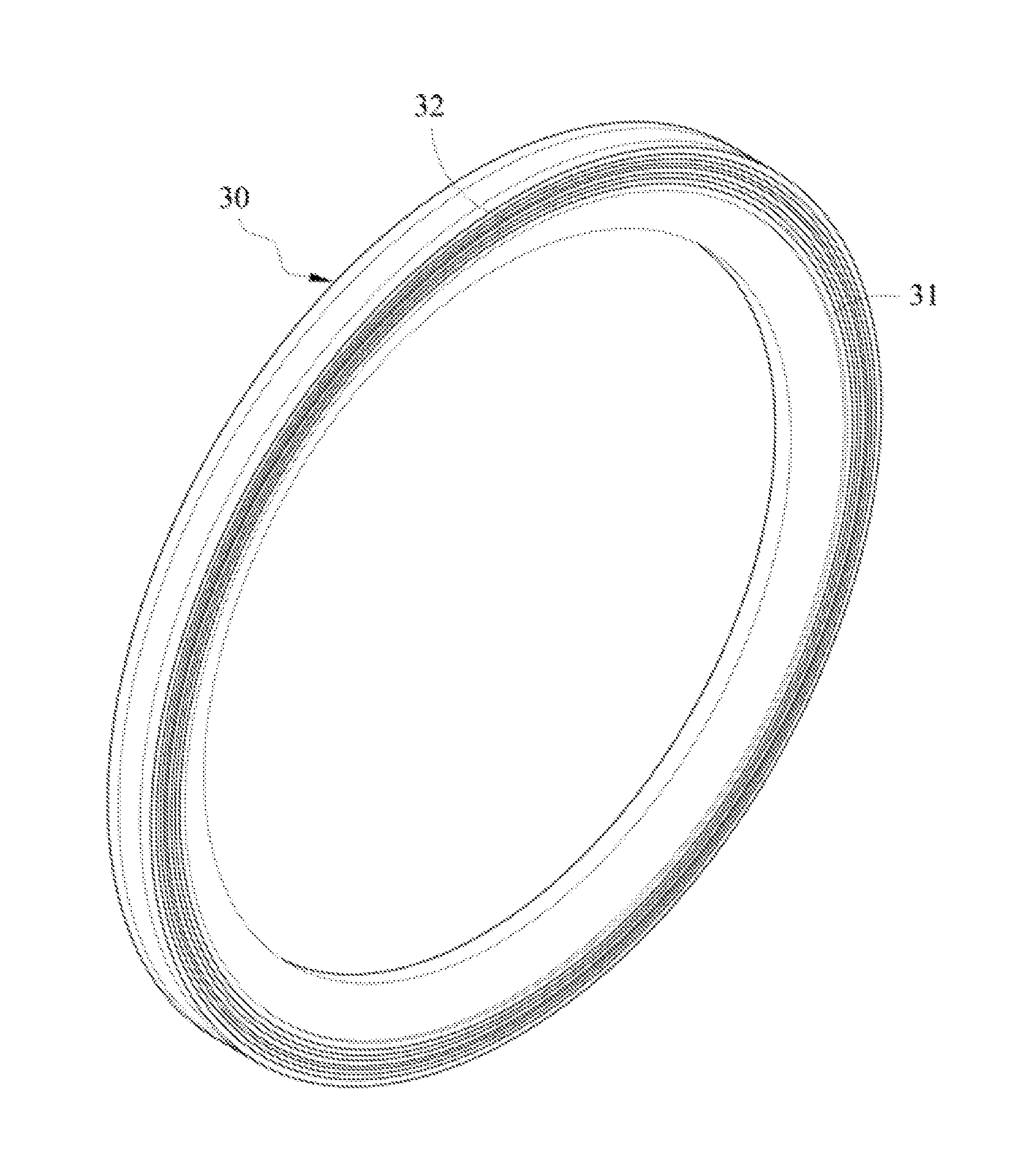
[0024]Referring to FIGS. 3, 4, 5A and 5B, the method for manufacturing a carbon fiber rim according to the present invention is as shown in FIG. 3.

[0025]At first, prepare a carbon fiber composite material and a thermosetting resin-based composite material. Next, prepare a rim-shaped mold for providing molding of the carbon fiber rim, and then place the carbon fiber composite material into the mold so that the carbon fiber composite material is distributed to form a pre-molded rim according to the mold. After the pre-molded rim is manufactured, take out the pre-molded rim from the mold, and then annularly affix the thermosetting resin-based composite material respectively to brake surfaces on both sides of the pre-molded rim, so as to form a brake layer 31.

[0026]Place the pre-molded rim back to the mold again and make the pre-molded rim and the thermosetting resin-based composite material integrally form a rim 30 by means of heat and pressure.

[0027]Take out the rim 30 having the brak...

third embodiment

[0031]FIG. 7 is a flowchart of the method for manufacturing a carbon fiber rim according to the present invention.

[0032]As shown in FIG. 7, at first, prepare a carbon fiber composite material. Next, prepare a rim-shaped mold for providing molding of the carbon fiber rim, place the carbon fiber composite material into the mold, make the carbon fiber composite material integrally form a rim 30 by means of heat and pressure, and then take out the rim 30.

[0033]Afterwards, perform first surface roughening treatment at the position of the brake layer 31 on both sides of the rim 30 by means of machining, and such a machining manner may be industrial blasting treatment or surface treatment is performed by mechanical means such as tools and machines so that the surface has an uneven appearance. After the first surface roughening treatment, coat a thermosetting resin-based composite material to the roughened surface so as to form a brake layer 31.

[0034]Before the brake layer 31 is hardened, s...

fourth embodiment

[0035]FIG. 8 is a flowchart of the method for manufacturing a carbon fiber rim according to the present invention.

[0036]As shown in FIG. 8, at first, prepare a carbon fiber composite material. Next, prepare a rim-shaped mold for providing molding of the carbon fiber rim, place the carbon fiber composite material into the mold, make the carbon fiber composite material integrally form a rim 30 by means of heat and pressure, and then take out the rim 30.

[0037]Afterwards, perform first surface roughening treatment at brake surface positions on both sides of the rim 30 by means of machining, and such a machining manner may be industrial blasting treatment or surface treatment is performed by mechanical means such as tools and machines so that the surface has an uneven appearance.

[0038]After the first surface roughening treatment, coat a thermosetting resin-based composite material to a roughened surface of the rim 30 so as to form a brake layer 31.

[0039]After the brake layer 31 is harden...


PUM

PropertyMeasurementUnit
shapeaaaaaaaaaa
heataaaaaaaaaa
pressureaaaaaaaaaa

Abstract

A method for manufacturing a carbon fiber rim is disclosed, which includes: preparing a carbon fiber composite material and a thermosetting resin-based composite material; preparing a mold to place the carbon fiber composite material into the mold so that the carbon fiber composite material forms a pre-molded rim according to the shape of the mold, and then annularly affixing the thermosetting resin-based composite material respectively to brake surfaces on both sides of the pre-molded rim, so as to form a brake layer; placing the pre-molded rim into the mold to integrally form a rim by means of heat and pressure; and taking out the rim having the brake layer on the surface.

Description

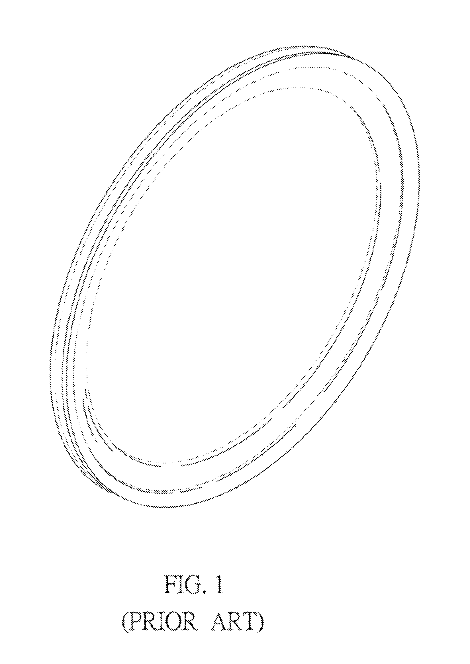
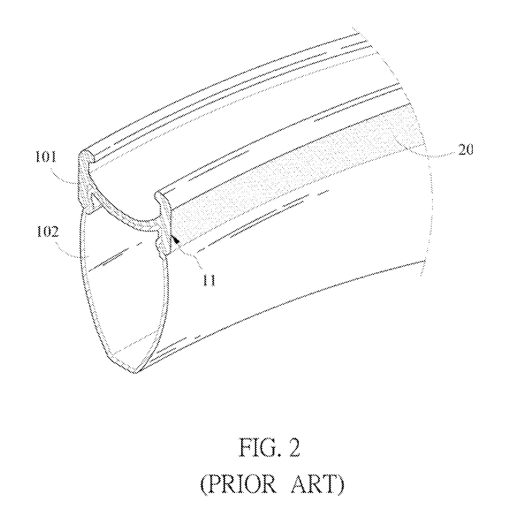
BACKGROUND OF THE INVENTION[0001]1. Field of Invention[0002]The present invention relates to a method for manufacturing a carbon fiber rim, and in particular, to a method for manufacturing a carbon fiber rim with a brake layer formed by a thermosetting resin-based composite material.[0003]2. Related Art[0004]Bicycles on the market generally use two types of brake, i.e., caliper brake and disc brake. The bicycle brake system using the caliper brake is widely used because of its simple structure, light weight and low price; moreover, as the bicycle tends to be light-weighted in recent years, the traditional aluminum alloy material has been gradually replaced by a carbon fiber composite material, which is widely used because in addition to the advantage of light weight, the carbon fiber composite material has high strength and good shock absorption. However, as shown in FIG. 1, the carbon fiber bicycle rim not only needs to support the cyclist's weight and the bicycle's weight, but als...

Claims


Application Information

Patent Timeline
Patent Type & Authority Applications(United States)
IPC IPC(8): B29C70/30B29C70/54B29D99/00
CPCB29C70/30B29D99/0032B29K2307/04B29L2031/32B29K2101/10B29C70/545B29L2031/3091B29L2031/322B29L2031/7482B29C70/747B60B5/02B60B21/08B60B2310/204B60B2360/368
Inventor TSAI, VINCECHIANG, MENG HUA
Owner TIEN HSIN INDS
Learn More