
Head-up display device

a display device and head-up technology, applied in the field of head-up display devices, can solve problems such as and achieve the effect of reducing the amount of sun light and preventing the breakage of liquid crystal display devices

Active Publication Date: 2015-04-09
NIPPON SEIKI CO LTD
View PDF3 Cites 40 Cited by
  • Summary
  • Abstract
  • Description
  • Claims
  • Application Information

AI Technical Summary

Benefits of technology

The present invention is about a head-up display device that can prevent the display from being damaged by sunlight. The device decreases the amount of sunlight that reaches the display, which reduces the chance of damage. Overall, this technology improves the durability of the head-up display device.

Problems solved by technology

Due to entering of the radiation to the display especially in the head-up display device, the liquid crystal of the liquid crystal display device becomes unable to display an image due to liquefaction of liquid crystal, and breaking of the liquid crystal display device may occur because of melting of polarizing plate.

Method used


Image

  • Head-up display device
  • Head-up display device
  • Head-up display device

Examples


first embodiment

[0022]With reference to attached drawings, the invention will be described below with an example of a head-up display device.

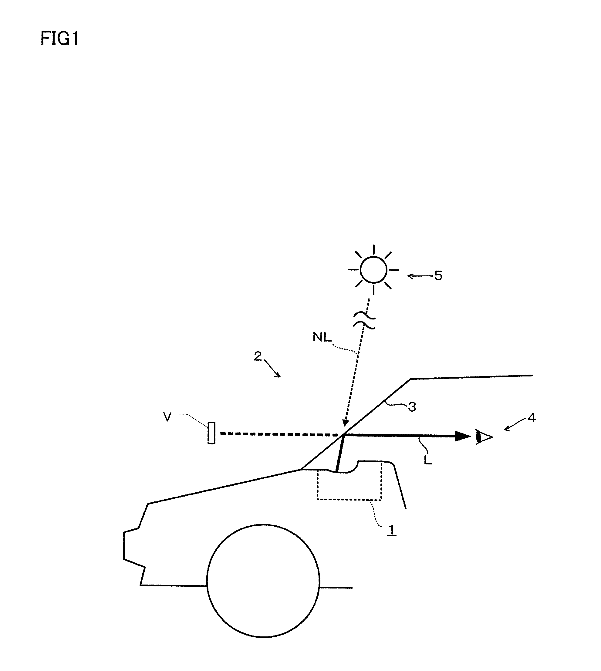
[0023]As shown in FIG. 1, a first embodiment of the head-up display device is situated in a dashboard of a vehicle and reflects an output light to a windshield 3 (a front glass) to display a virtual image V of a vehicle information and the virtual image V is then visually recognized by a driver. The driver can read the information without moving his / her eye sight from its direction side.

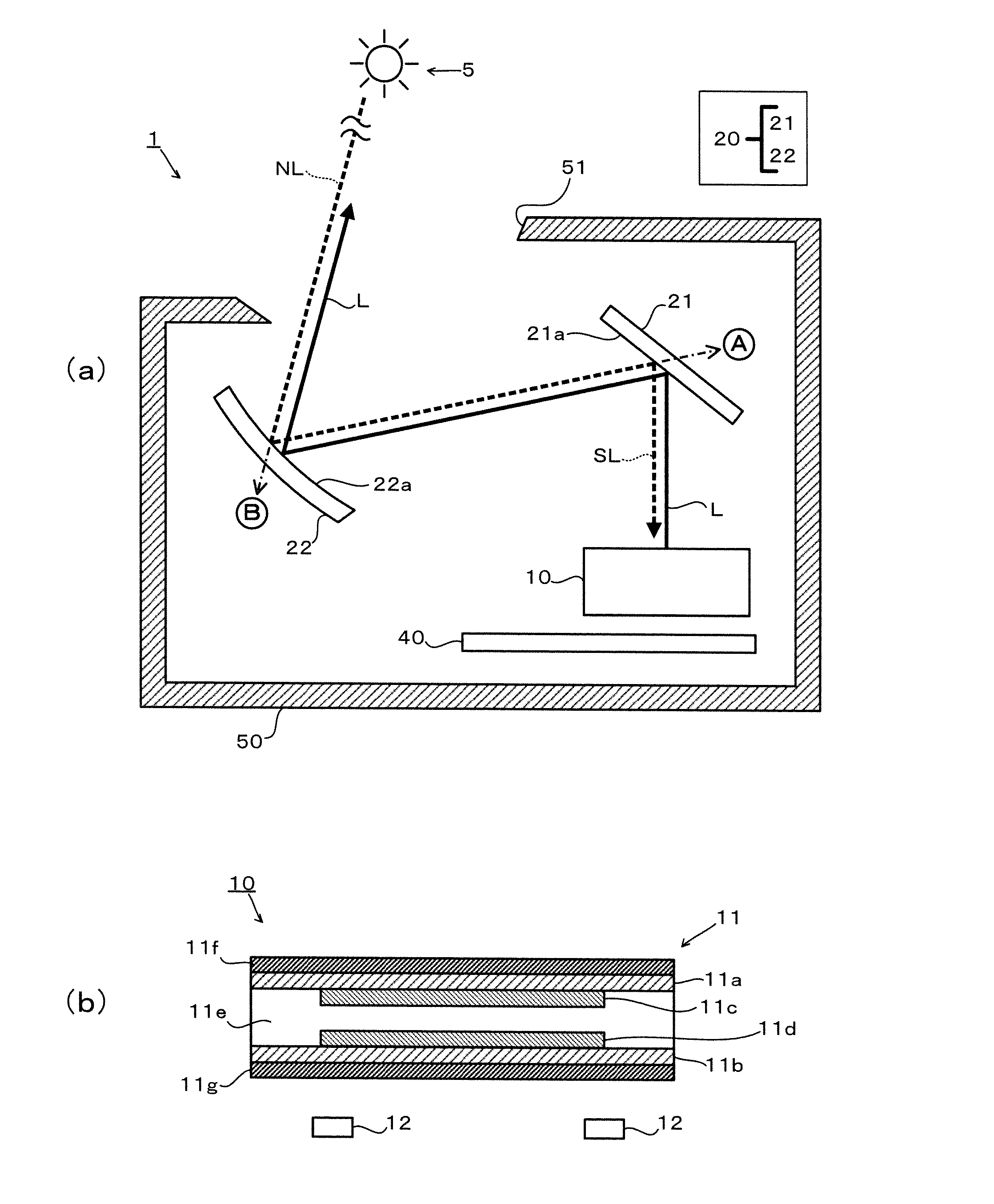
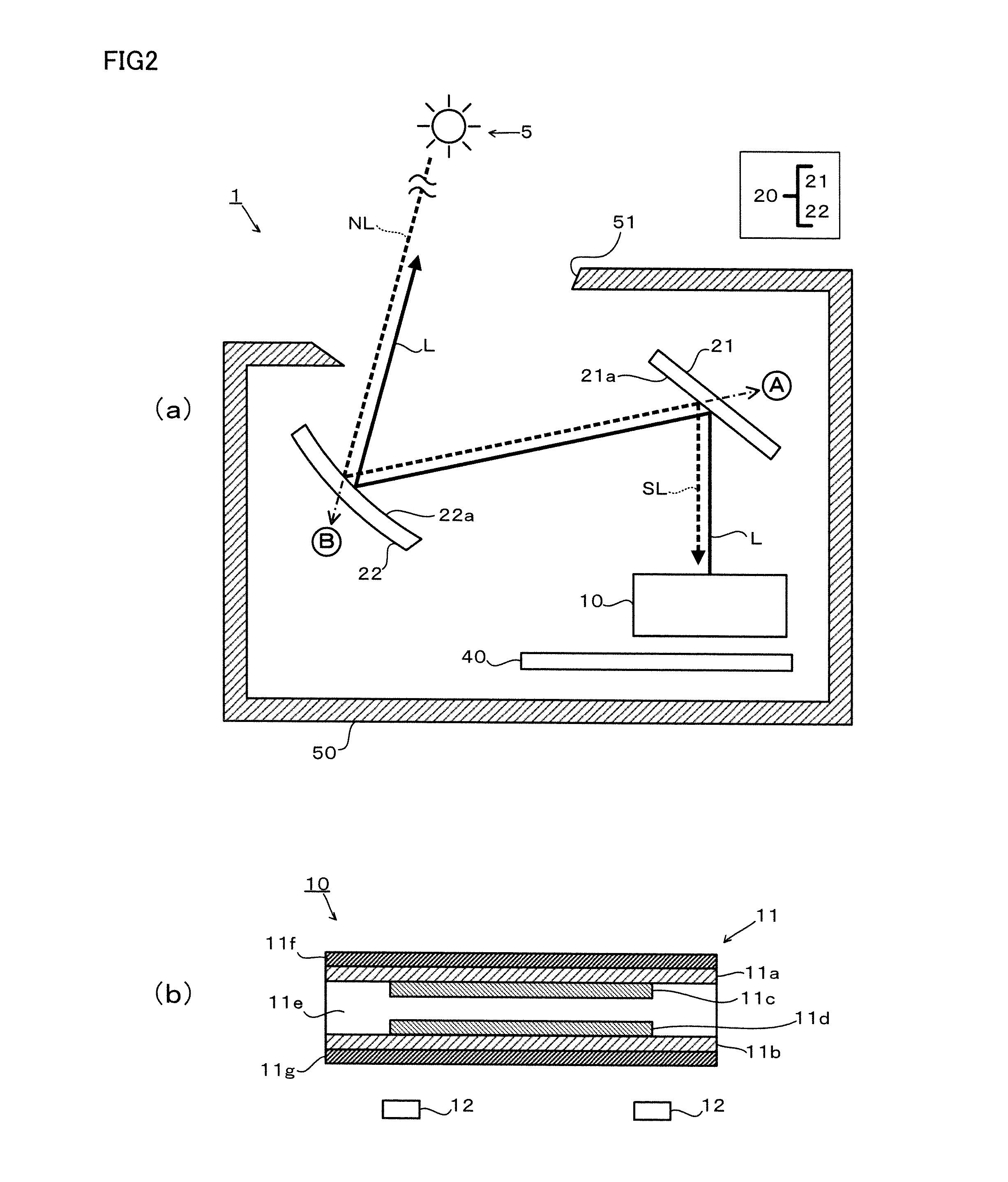
[0024]The head-up display device 1 comprises a liquid crystal display device 10, an optical system 20, a detection portion 30, a circuit board40 including a control unit 41 and a housing 50.

[0025]The liquid crystal display device 10 radiates a natural light L to display an image to notify vehicle information. The liquid crystal display device 10 consists of a well known transparent type liquid crystal display device and including a liquid crystal panel 11 and a backlight 12.

[00...

second embodiment

[0037]In FIG. 2 (a), only the direction of where the detection unit 30 is shown to describe the structure. A unit B shown in this figure describes the position of the detection unit in

[0038]The circuit board 40 is formed of glass reinforced plastics with copper tracks in the place of wires. The circuit board 40 is placed at the opposite side of the light emission side of the liquid crystal display device 10. The backlight 12 and the control unit 41 are assayed and electrically connected to the liquid crystal display device 10 and detection unit 30 through flexible printed circuit.

[0039]The control unit 41 is comprised of microcomputer including memory means of CPU (Central Processing Unit) ROM (Read Only Memory) and RAM (Random Access Memory), and timer device. A program for executing the display control processing is stored the ROM of the control unit 41 in advance and the CPU reads out the memory.

[0040]The circuit board 40 is assayed with drive circuit to drive an amplification ci...


PUM


Abstract

Provided is a head-up display (HUD) device capable of effectively preventing damage to a liquid-crystal display device due to entry of exterior light. A HUD device has a liquid-crystal panel, and is provided with a liquid-crystal display device for realizing a transparent display using light from a backlight, a control means for controlling the liquid-crystal display device, and an optical system for reflecting the display light outputted by the liquid-crystal display device onto a windshield. A flat mirror constituting the optical system allows infrared rays of incident light to pass behind the mirror and reflects the visible light. The HUD device is provided with an infrared-ray sensor positioned behind the flat mirror, and the control means reduces the brightness of the light of the backlight or extinguishes the backlight when the strength detected by the infrared-ray sensor exceeds a predetermined threshold.

Description

TECHNICAL FIELD[0001]The present invention relates to a head-up display device.BACKGROUND ART[0002]Conventionally, a head-up display device has been developed to display an image of vehicle information to a front glass of the vehicle so that a driver can read the information without moving his / her eye sight from its direction side. The head-up display device for a vehicle radiates a display light to the windshield and makes the driver to visually recognize a virtual image obtained by the radiation.[0003]Due to entering of the radiation to the display especially in the head-up display device, the liquid crystal of the liquid crystal display device becomes unable to display an image due to liquefaction of liquid crystal, and breaking of the liquid crystal display device may occur because of melting of polarizing plate.[0004]A head-up display device disclosed in Patent Literature 1 has been known. On the front side of the display of the head-up display device, a polarizing member and t...

Claims


Application Information

Patent Timeline
IPC IPC(8): G02B27/01G02F1/1335G01J1/42G02F1/133
CPCG02B27/0101G02F1/13306G02F1/133528G02B5/281G02F1/133555G01J1/42G02B2027/0118G02F1/133603G02B27/01G02B2027/0112G09G3/3406G09G2360/144
Inventor SATO, GENICHIROFURUSAWA, HIROYUKIITAGAKI, MASAOSEKIGUCHI, TAKUYA
Owner NIPPON SEIKI CO LTD
Learn More