Bi-Polarized Broadband Annular Radiation Unit and Array Antenna

a broadband annular radiation unit and broadband technology, applied in the field of antennae, can solve the problems of large weight and high production cost, and achieve the effects of reducing the weight of the product, simple structure, and good stability

Active Publication Date: 2015-04-16
ANHUI MOBILE COMM +1
View PDF2 Cites 14 Cited by
  • Summary
  • Abstract
  • Description
  • Claims
  • Application Information

AI Technical Summary

Benefits of technology

[0024]At first, the bi-polarized broadband annular radiation unit of the invention has simple structure and may be fabricated using aluminum by sheet metal stamping forming process or casting process and therefore it has good stability. Moreover, the weight of the product is further reduced such that uniformity is maintained for the product.
[0025]Secondly, the bi-polarized broadband annular radiation unit of the invention is made using sheet metal stamping forming process or casting process both of which are simple and inexpensive due to radiation unit of a single line sheet design.
[0026]Lastly, when the adjacent loading lines of the adjacent dipoles of the bi-polarized broadband annular radiation unit of the invention are orthogonally arranged, irrelevancy between two polarizations is improved; separation and radiation characteristics between two polarizations such as cross polarization resolution and the like are enhanced as well.

Problems solved by technology

Though in terms of electric performance this kind of radiation unit brings contribution to the pertinent art, it suffers from large weight and high production cost due to formation by casting zinc alloy.
It is a challenge for person of the art to apply this sheet metal stamping forming process and realize electrical performance of the radiation unit.

Method used


Image

  • Bi-Polarized Broadband Annular Radiation Unit and Array Antenna
  • Bi-Polarized Broadband Annular Radiation Unit and Array Antenna
  • Bi-Polarized Broadband Annular Radiation Unit and Array Antenna

Examples


first embodiment

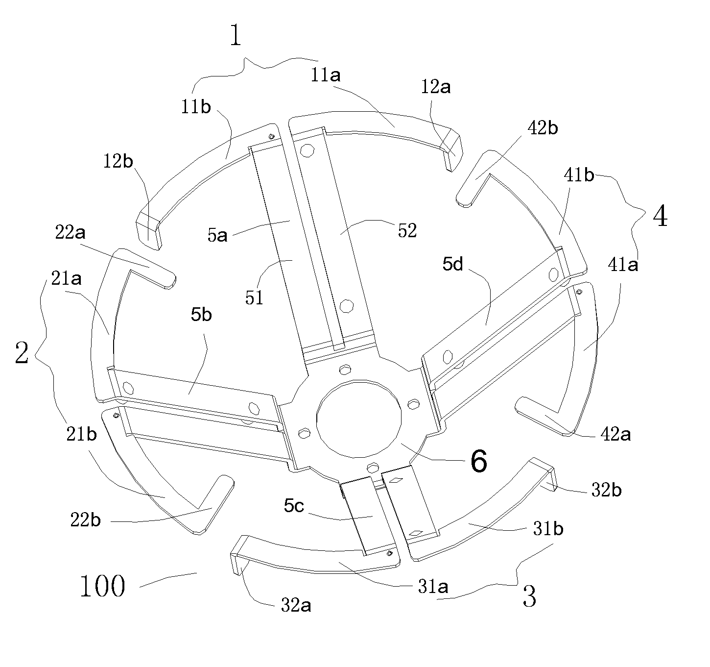
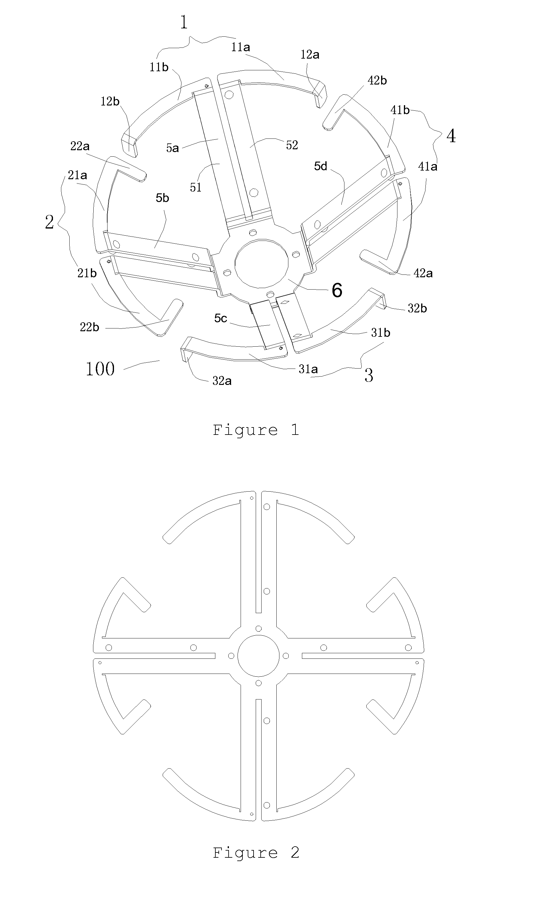
[0044]With reference to FIGS. 1, 2 and 3, according to a bi-polarized broadband annular radiation unit of the invention, a radiation unit 100 includes two pairs of dipoles. Each pair of the dipoles includes two dipoles which are symmetrically and oppositely arranged. Each dipole is a vibrator unit and therefore, there are totally four vibrator units 1, 2, 3, and 4. Here, the vibrator units 1 and 3 are symmetrical about each other, and vibrator units 2 and 4 are also symmetrical about each other, thus achieving assembling of the radiation unit in a polarization-orthogonal manner.

[0045]In this case, each vibrator unit includes two unit arms one end of each unit arm is opposite to and separated from one end of the other unit arm. Each unit arm is of a single line sheet design. A distal end of each unit arm of the vibrator unit is provided with a loading line. The distal end of one unit arm is far away from a corresponding distal end of the other unit arm. The vibrator units 1-4 are hel...

second embodiment

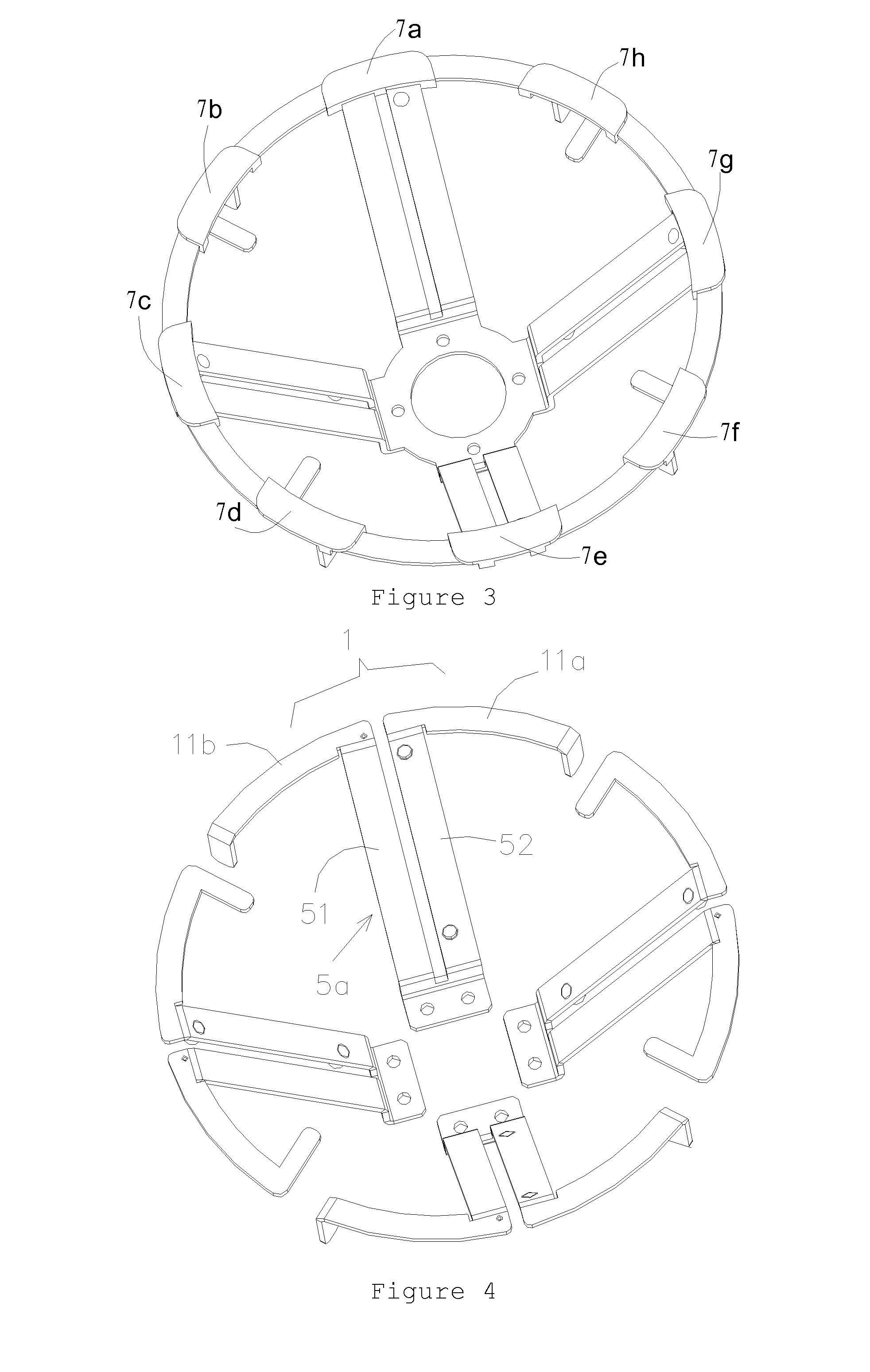
[0049]In this embodiment, regarding the entire radiation unit 100, all its component including all vibrator arms and balun arms are suitable held in place by eight plastic holding clips 7a, 7b, 7c, 7d, 7e, 7f, 7g, and 7h, thus all the vibrator arms and balun arms of the radiation unit being formed as an entity, maintaining relative locations among these vibrator arms and balun arms, and dramatically improving structural strength of the radiation unit. Reference is made to FIG. 4. According to a bi-polarized broadband annular radiation unit of the invention, the same construction as that disclosed in aforementioned embodiment is employed. There is also difference in this embodiment. A component consisted of a vibrator unit 1 and a corresponding balun arm (such as balun arm 5a), in other word, consisted of two unit arms (for example arms 11a and 11b) of the same vibrator unit (such as unit 1) and two balun lines 51 and 52 of the same balun arm, is an integral and independent component...

third embodiment

[0050]Reference is made to FIG. 5. According to a bi-polarized broadband annular radiation unit of the invention, the same construction as that disclosed in aforementioned embodiments is employed. The difference lies in implementation of respective unit arm. All the unit arms of the entire radiation unit 100 (such as unit arms 11a and 11b) each have an adjusting block 110 at a corresponding symmetrical location. In this embodiment, the adjusting block 110 is of a disk shape.

[0051]Reference is made to FIG. 6. According to a fourth embodiment of a bi-polarized broadband annular radiation unit of the invention, the same base and balun arm are used as those disclosed in the first or second embodiment of the invention. The difference lies in implementation of the vibrator loading lines. Here, the loading lines (such as those labeled 12a and 12b) of a pair of dipoles 1 and 3 are vertically downwardly orientated, while the loading lines (such as those labeled 42a and 42b) of another pair o...


PUM


Abstract

A bi-polarized broadband annular radiation unit, for being installed on a metal reflective plate thus constituting a communication antenna and defining an annular construction by two pairs of orthogonally polarized dipoles, includes two pairs of orthogonally polarized dipoles, each dipole comprising two symmetrical unit arms of a single line sheet shape, one end of a unit arm being facing to a corresponding end of the other unit arm, and a distal end of each unit arm of at least one pair of dipoles is provided with a loading line; and a plurality of balun arms feeding power to and supporting respective dipoles, each balun arm including two parallel balun lines, and the top ends of the two balun lines being connected with corresponding ends of the two unit arms of a corresponding dipole. Each unit arm and the balun line and/or loading line connected to the same unit arm are made by sheet metal stamping forming process or casting process.

Description

FIELD OF THE INVENTION[0001]The invention relates to antennae used in mobile communications and more particularly, relates to a bi-polarized broadband annular radiation unit and a single frequency and dual frequency broadband array antennae incorporating the radiation unit.BACKGROUND OF THE INVENTION[0002]Currently, a bi-polarized broadband annular radiation unit is mainly formed by casting of zinc alloy. For example, Chinese Patent Application No.: CN101425626A filed by the present applicant Comba communication system (China) Ltd. and published on May 6, 2009 discloses bi-polarized broadband annular radiation unit. It includes the following parts: two pairs of orthogonally polarized dipoles for transmitting or receiving communication signals; and a balancer corresponding to each dipole for feeding power to the dipole in a balanced manner. Each dipole includes two unit arms symmetrically mounted on the respective balancer. Two arms are linearly symmetrical about the balancer. One en...

Claims


Application Information

Patent Timeline
Patent Type & Authority Applications(United States)
IPC IPC(8): H01Q21/26H01Q19/10
CPCH01Q21/26H01Q19/108H01Q1/246H01Q5/42H01Q21/08H01Q21/24H01Q25/001
Inventor LIU, PEITAOWANG, QINYUANSUN, SHAN QIUHUANG, LIWENZHANG, YINGCHUNTANG, QING
Owner ANHUI MOBILE COMM
Why Eureka
Try Eureka