
Method and system for passive detection, localization and characterization of mechanical wave sources using ultrasonic guided waves

a technology of mechanical wave source and ultrasonic guided wave, which is applied in the field of passive detection, localization and characterization of mechanical wave source using ultrasonic guided wave, and can solve problems such as structural complexity, requiring propagation velocity profiles, and complicated source localization approaches

Active Publication Date: 2015-04-16
HIDDEN SOLUTIONS
View PDF2 Cites 5 Cited by
  • Summary
  • Abstract
  • Description
  • Claims
  • Application Information

AI Technical Summary

Benefits of technology

The patent describes a method and system for estimating the response of a structure to mechanical waves at specific points on the structure. The system includes sensors (also known as transducers) that are placed on the structure and are able to record signals caused by mechanical waves. These signals are used to compute a spatial channel impulse response estimate, which can help to detect, localize, and characterize the source of the mechanical waves. This information can be useful in identifying areas of damage or performing other types of non-destructive testing on the structure. The method involves comparing data collected from the transducers with known excitation functions and using techniques such as cross-correlation, deconvolution, and weighted cross-correlation to estimate the impulse response at each point on the structure. The system can include a movable transducer or multiple transducers placed at different locations on the structure to increase the accuracy and resolution of the impulse response estimates. Overall, the invention provides a way to efficiently and accurately detect and characterize mechanical waves on a structure.

Problems solved by technology

The detection problem is largely associated with discriminating acoustic or elastic waves emanating from sources of interest from acoustic or elastic waves originating from benign environmental or operational sources.
While direct path techniques work well for simple structures, such as pressure vessels, this simplified approach to source localization becomes problematic in complex structures, particularly for AE systems that use dispersive guided waves to monitor large, complex, plate-like structures.
Structural complexity can result from any number of geometric features, including cut-outs, stiffeners, rivets, thickness variations, and anisotropic materials (e.g. carbon-fiber reinforced plastics).
When a structure is complex, guided waves travel in very complex paths via multiple modes and there is often not a direct path between a potential source location and sensors.
Another problem with triangulation TDOA methods is that they require propagation velocity profiles for accurate and reliable source localization.
Calibration data, however, is often obtained through tedious and error-prone manual measurements of received waveforms using, for example, pencil break, glass capillary break, or active transducer sources, which can be very costly and limit localization performance.
Characterization of sources is often problematic, and is usually achieved by ad hoc methods that attempt to correlate measured signal characteristics (e.g., duration, center frequency, etc.) with different damage mechanisms.
Localization challenges that arise from structural complexities can be mitigated with high sensor density, but this approach is usually not economically viable because of the increased cost and weight.
These methods are problematic from several different perspectives.
First, since performance is sensitive to training and calibration data, it is difficult to quantify expected performance.
Second, there is a discomforting lack of insight into the trained systems since artificial intelligence methods generally do not result in a set of intuitive rules that can be explained, justified, or even documented.
Finally, there is a relatively high level of operator training required in order to effectively and reliably train and interpret artificial intelligence systems, which increases the cost and complexity of effective implementation.

Method used


Image

  • Method and system for passive detection, localization and characterization of mechanical wave sources using ultrasonic guided waves
  • Method and system for passive detection, localization and characterization of mechanical wave sources using ultrasonic guided waves
  • Method and system for passive detection, localization and characterization of mechanical wave sources using ultrasonic guided waves

Examples


Embodiment Construction

[0031]Some embodiments of the invention are discussed in detail below. In describing embodiments, specific terminology is employed for the sake of clarity. However, the invention is not intended to be limited to the specific terminology so selected. A person skilled in the relevant art will recognize that other equivalent components can be employed and other methods developed without departing from the broad concepts of the invention. All references cited herein are incorporated by reference as if each had been individually incorporated.

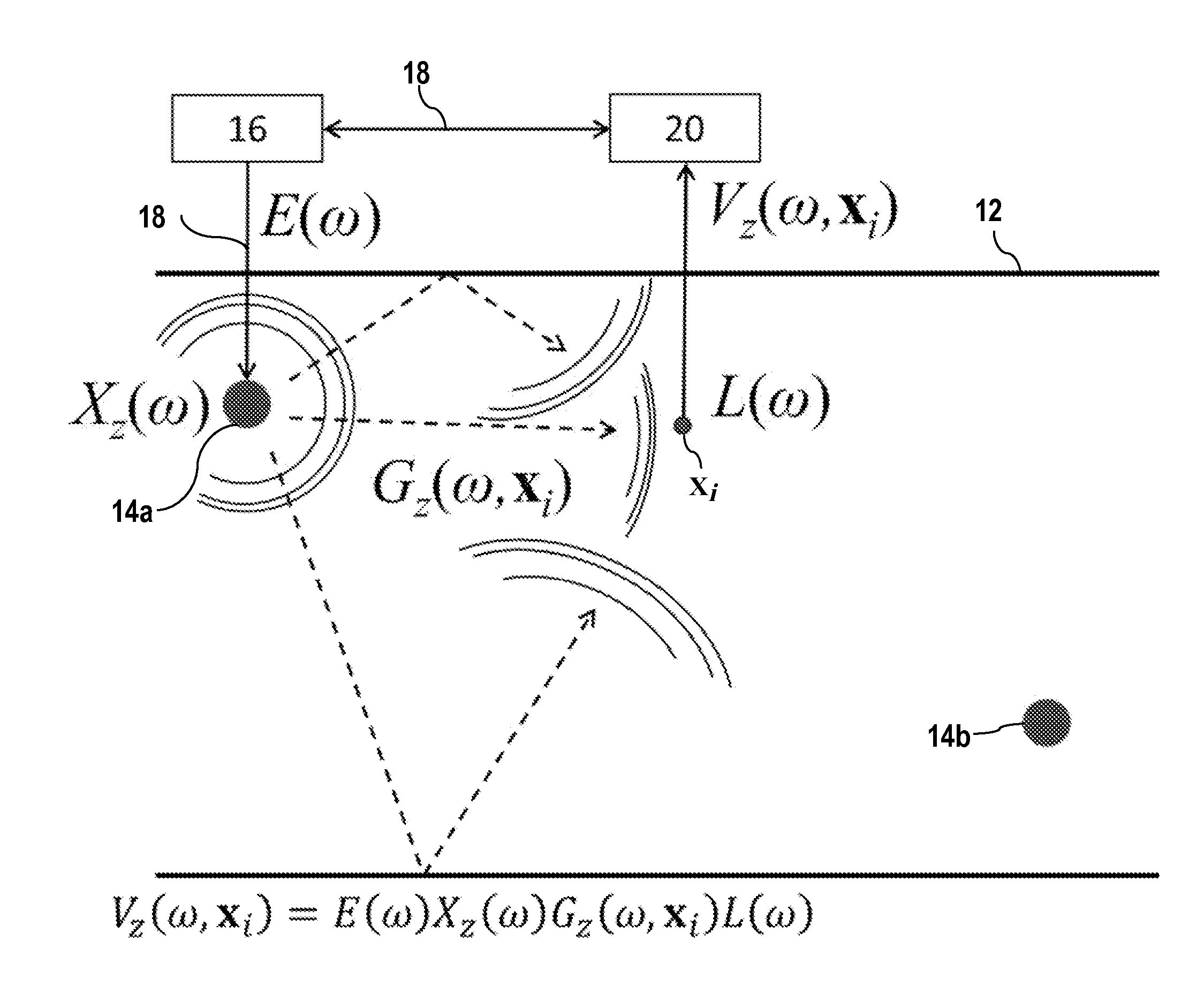
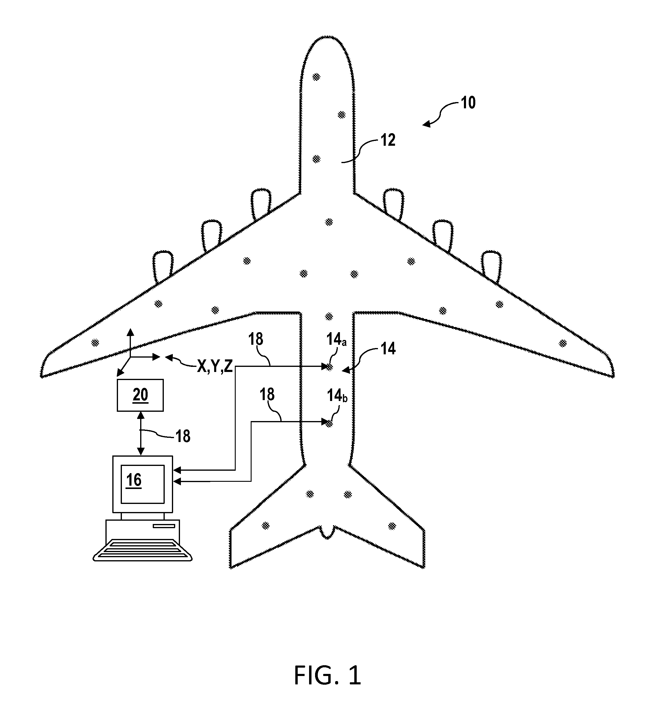
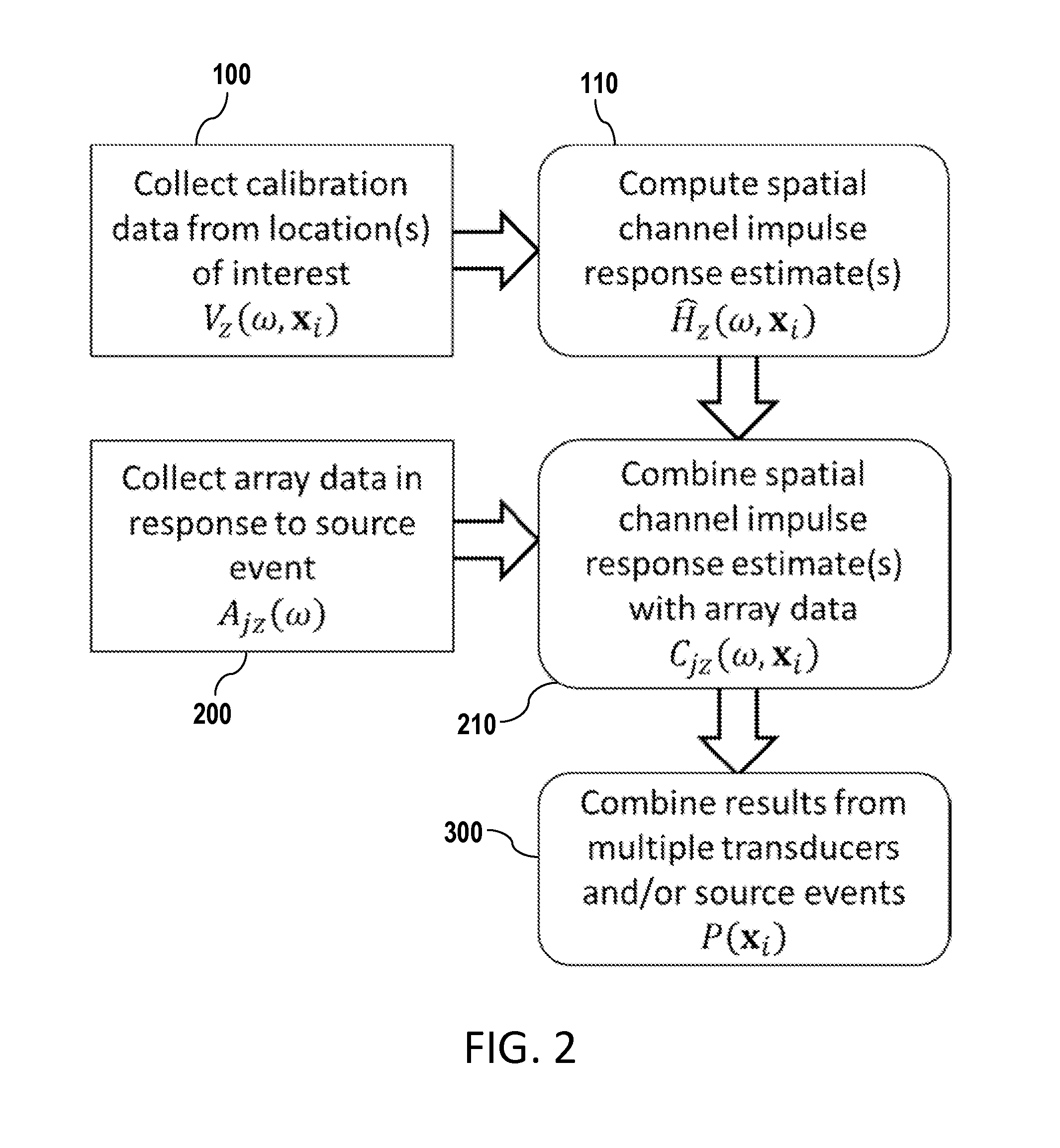
[0032]FIG. 1 is a schematic representation of a system 10 for multi-path passive detection, localization and / or characterization of mechanical wave sources using ultrasonic guided waves according to an embodiment of the invention. As shown in FIG. 1, the system 10 may include a spatially distributed array 14 of transducers 14a, 14b, etc., mounted on a structure 12 such as, for example but not limited to, an aircraft structure. Other structures may in...


PUM

PropertyMeasurementUnit
mechanical waveaaaaaaaaaa
frequencyaaaaaaaaaa
elasticaaaaaaaaaa

Abstract

A method and system for passively detecting, localizing, and / or characterizing a mechanical wave source at one or more spatial points of interest on a structure using ultrasonic guided waves are provided. The method includes estimating the spatial channel impulse response at one or more spatial points of interest using a movable transducer. Collected data recorded in response to transient mechanical waves is then combined with the spatial channel impulse response estimates to detect, localize, and / or characterize the source. A direct path from the mechanical wave source to each transducer is not required. Anisotropies and variations between transducer transfer functions may be accounted for and all propagation paths may be used to perform source localization. The method and system may leverage structural complexity rather than ignore it.

Description

CROSS-REFERENCE TO RELATED APPLICATIONS[0001]This application claims the priority benefit of U.S. Provisional Application No. 61 / 647,763, filed May 16, 2012, entitled “Multi-Path Passive Source Localization with Ultrasonic Guided Waves,” the entirety of which is hereby incorporated by reference.BACKGROUND[0002]1. Field of Invention[0003]The invention relates generally to methods and systems for detection, localization, and characterization of defects in a structure, and more particularly, to a method and system for passive detection, localization, and characterization of mechanical wave sources using ultrasonic guided waves.[0004]2. Discussion of Related Art[0005]Acoustic emission (AE) technology has been used for over 50 years to detect and track the initiation or growth of material defects. At the most fundamental level, acoustic emission systems may use permanently attached sensors to provide continuous monitoring of a structure in an attempt to record and analyze transient mecha...

Claims


Application Information

Patent Timeline
Patent Type & Authority Applications(United States)
IPC IPC(8): G01N29/36G01N29/34G01N29/04
CPCG01N29/36G01N29/04G01N29/34H04W52/0216G01N29/043G01N29/2475G01N29/30G01N29/4427G01N29/4472G01N2291/0425G01N2291/2694H04W4/027H04W52/0251Y02D30/70G01M5/0033G01N2291/0258G01M5/0066
Inventor HALL, JAMES STROMANMICHAELS, JENNIFER EMMONS
Owner HIDDEN SOLUTIONS
Learn More