
Multiple zone control system and method of operation

a control system and multi-zone technology, applied in lighting and heating apparatus, heating types, instruments, etc., can solve the problems of increasing equipment life, reducing cycling, and increasing the amount of time the boiler operates in the condensing, so as to reduce the cycle, reduce the amount of time the boiler is operated, and improve the efficiency of the boiler.

Inactive Publication Date: 2015-04-23
BURNHAM SERVICES
View PDF21 Cites 28 Cited by
  • Summary
  • Abstract
  • Description
  • Claims
  • Application Information

AI Technical Summary

Benefits of technology

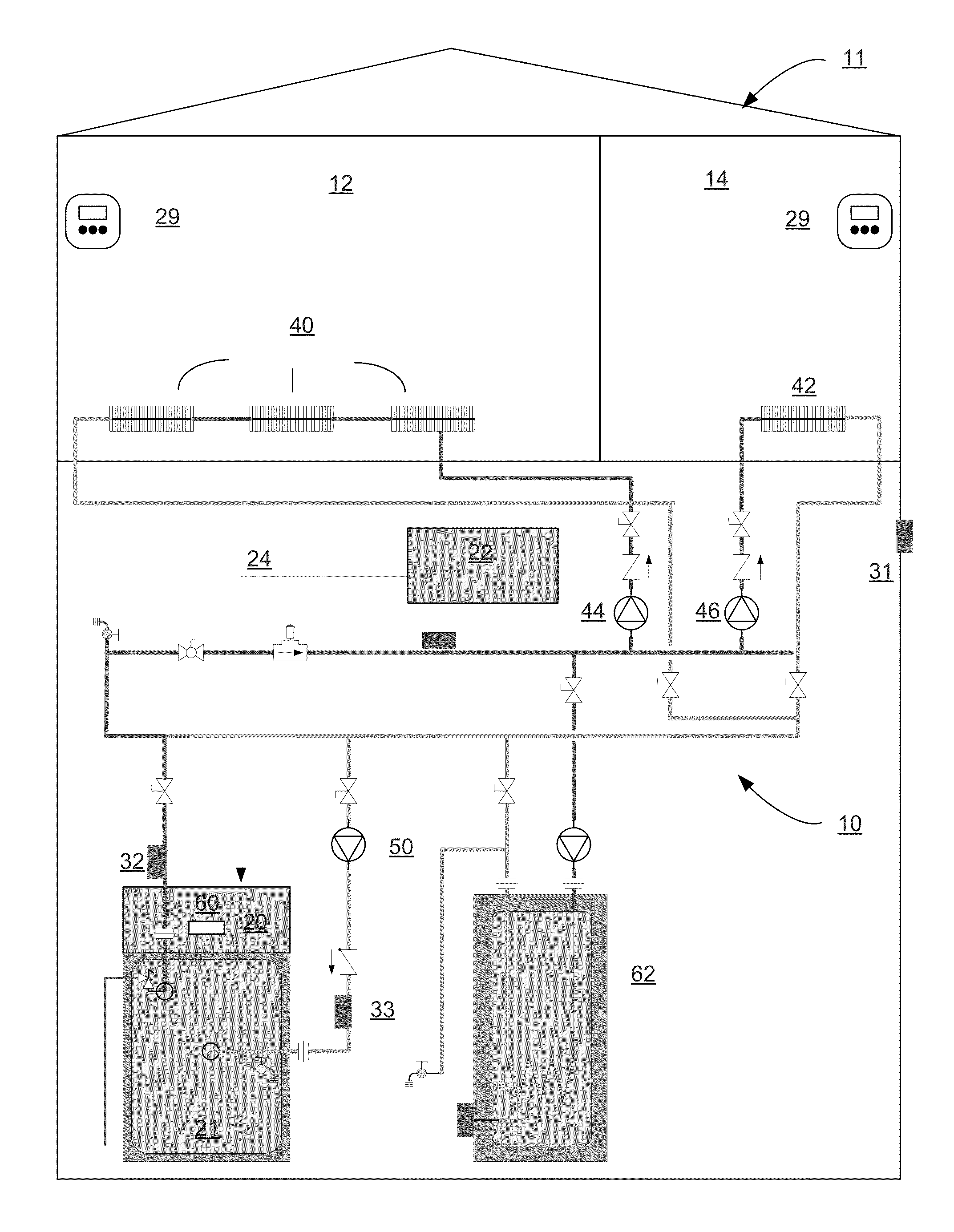
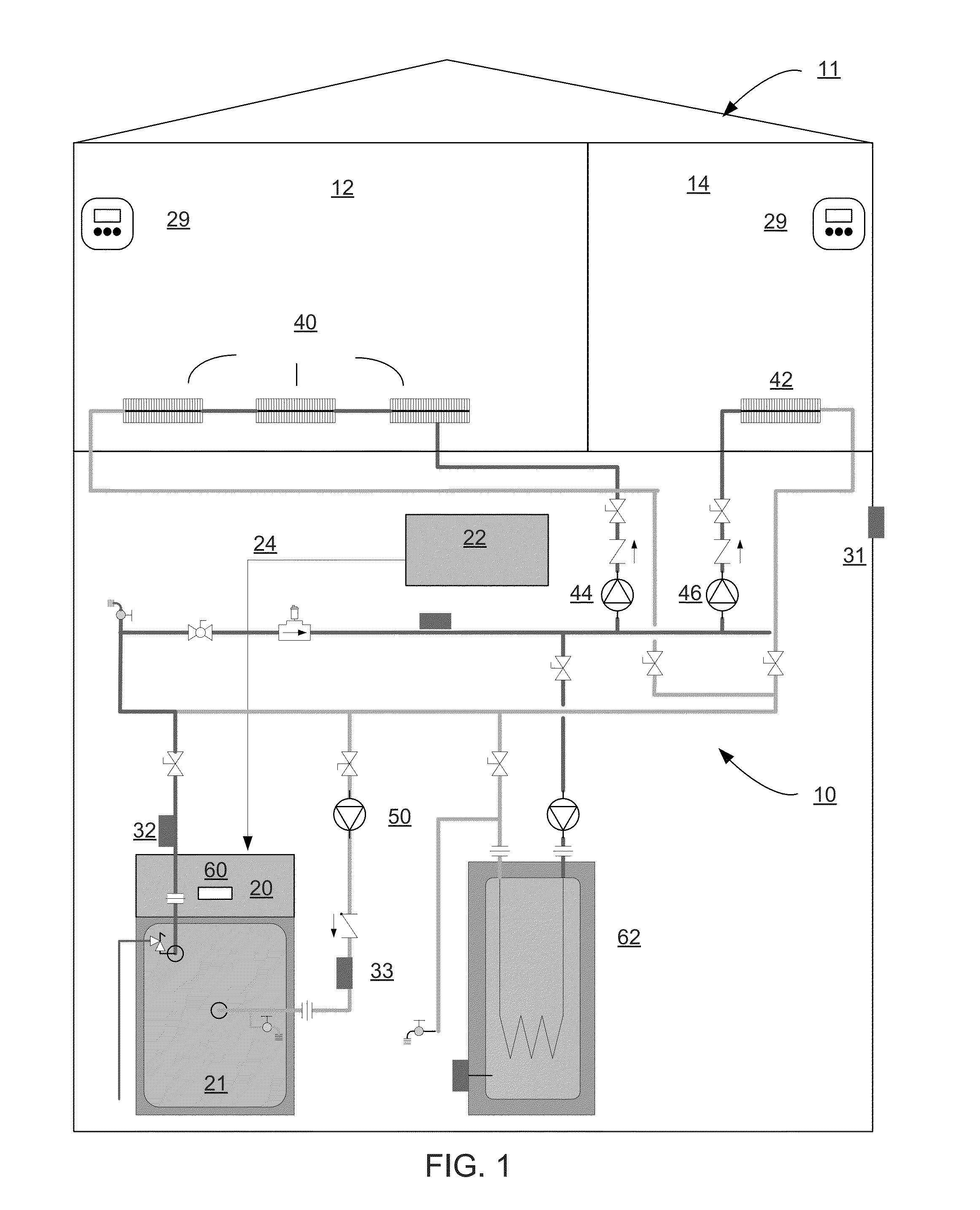
This patent describes a heating / cooling system that can provide the appropriate amount of heat / cooling to each individual zone without wasting energy. The system uses adaptive firing rate control, which takes into account the likely heat loss for a given zone and adjusts the boiler firing rate accordingly. This control system optimizes the condensing boiler firing rate by preventing it from driving too high based on measuring temperature alone. Overall, the system reduces the number of boiler cycles, extends the lifespan of the equipment, and saves fuel by efficiently distributing heating capacity to the zones.

Problems solved by technology

The result is a significantly increased amount of time the boiler operates in the condensing mode, reduced cycling, increasing equipment life and saving fuel.

Method used


Image

  • Multiple zone control system and method of operation
  • Multiple zone control system and method of operation
  • Multiple zone control system and method of operation

Examples


Embodiment Construction

[0017]The present invention will be described more fully hereinafter with reference to the accompanying drawings, in which illustrative embodiments of the invention are shown. In the drawings, the relative sizes of regions or features may be exaggerated for clarity. This invention may, however, be embodied in many different forms and should not be construed as limited to the embodiments set forth herein; rather, these embodiments are provided so that this disclosure will be thorough and complete, and will fully convey the scope of the invention to those skilled in the art.

[0018]It will be understood that spatially relative terms, such as “top”, “upper”, “lower” and the like, may be used herein for ease of description to describe one element's or feature's relationship to another element(s) or feature(s) as illustrated in the figures. It will be understood that the spatially relative terms are intended to encompass different orientations of the device in use or operation in addition ...


PUM


Abstract

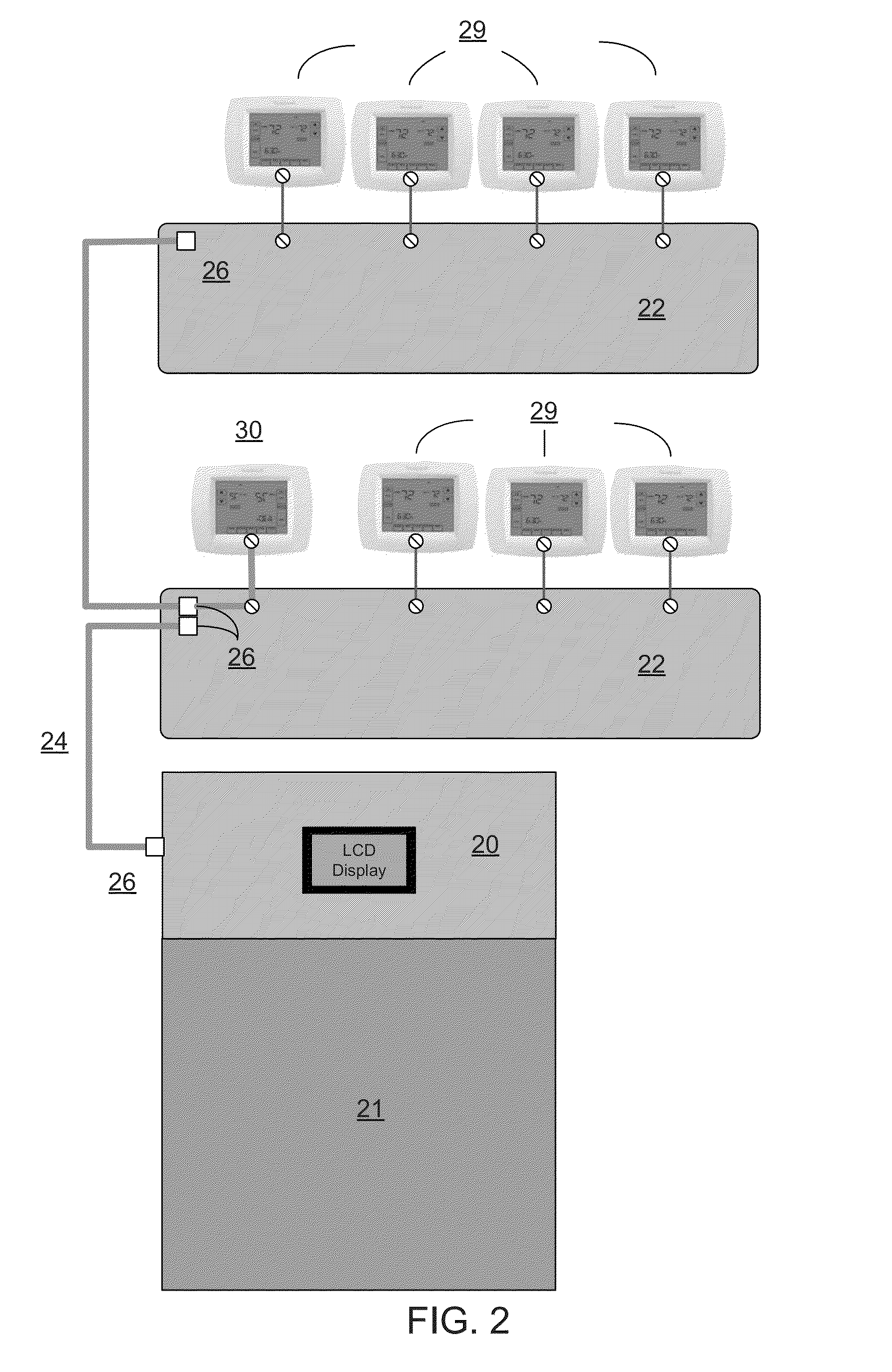
A multiple heating / cooling zone control system is disclosed. A heating / cooling system control device continuously monitors heating / cooling zone demand and matches the heating / cooling device output capacity to the total space or heat input required. Within the calculated heating / cooling device output capacity the heating / cooling device is modulated based on zone temperature setpoint to further adjust heating / cooling device output. As heat / cooling loss is increased heating / cooling device capacity and modulation are increased. Should heat / cooling loss decrease heating / cooling device capacity and modulation are decreased. Since heat / cooling output is adjusted based on the heat loss(gain) the heating / cooling device can be immediately adjusted to the proper or matching heating / cooling rate even before water / air temperature based adjustments can be made. Hence, the overall effect of the control device is a reduction in cycles of the heating / cooling device and the life of the heating / cooling device is extended and subsequent energy is saved.

Description

FIELD OF THE INVENTION[0001]The present invention relates generally to a multiple zone control system for controlling heating and / or air conditioning and a method of operation thereof. In particular, the invention is directed to the control and operation of multiple heating (cooling) zones for single and multiple family residences.BACKGROUND OF THE INVENTION[0002]Boiler systems have been used to regulate the temperature of commercial and residential facilities for a number of years. However, despite the fact that boiler systems have been around for many years, innovations continue to change the manner in which these systems operate.[0003]The first residential boilers were coal or wood fired and were always “on”. The resulting over or under heating was corrected by opening a window, putting on a sweater and adding more or less fuel the next day. Next the industry introduced the “on / off” boiler that turned “on” the boiler when the home was cold and turned it “off” after it became warm...

Claims


Application Information

Patent Timeline
Patent Type & Authority Applications(United States)
IPC IPC(8): F24F11/00F24D3/02F24D19/10F24F3/00
CPCF24F11/0012F24F11/0034F24F3/00F24F2011/0013F24F11/0086F24D3/02F24D19/1003F24F11/0076F24D19/1009F24D19/1012F24D2220/04F24F11/30F24F2110/10F24F2110/12F24F2120/10F24F11/70Y02B30/70F24F11/52F24F11/85F24F2120/00F24F11/46F24F11/63F24F2140/00F24H15/212F24H15/36F24H15/258F24H15/269F24H15/174F24H15/395F24H15/457F24H15/265
Inventor CLOONAN, PETER MICHAELDREW, CHRISTOPHER READ
Owner BURNHAM SERVICES
Learn More