Heat pump system using latent heat

a heat pump and latent heat technology, applied in the field of heat pump systems, can solve the problems of large installation space, difficult to pump back ice formed by latent heat extraction into separate injection wells, and specific heat can be extracted, etc., and achieve the effect of lack of building spa

Active Publication Date: 2015-04-30
VGE
View PDF20 Cites 18 Cited by
  • Summary
  • Abstract
  • Description
  • Claims
  • Application Information

AI Technical Summary

Benefits of technology

[0056]In an embodiment of the present invention, the heat pump system may additionally comprise a cooling circuit.
[0057]Such cooling circuit (K) may be adapted for delivering cold to a consumer by circulating liquid and / or ice slurry stored in the reservoir as illustrated in FIG. 3. For example in summer, when the temperature of the soil is lower than the ambient temperature, the liquid having soil temperature, may be circulated for cooling a consumer's premises, while keeping heating the consumer's domestic water.
[0058]As illustrated in FIG. 4, such cooling circuit (K) may be adapted not only for delivering cold to a cold consumer (D), but also for delivering heat to the reservoir. In this case a refrigerating or air-conditioning system may be implemented for extracting heat at a cold consumer's premises.
[0059]In a particular embodiment, the cold consumer and the heat consumer may be the same entity, for example a consumer extracting heat from its refrigerating and freezing rooms, storing the heat in the reservoir, and delivering at least part of it to rooms to be heated.
[0060]In accordance with the present invention, the heat pump system may comprise a plurality of heat-exchangers, a plurality of second circuits for delivering heat to a plurality of heat consumers, and a plurality of first circuits circulating liquid stored in a common reservoir. Optionally, the plurality of heat-exchangers may be installed at the premises of the plurality of heat consumers. For example each individual heat consumer may have an individual heat-exchanger installed (and a circulation pump) and appropriate tubing for extracting heat from a common reservoir (e.g. a common rain water collector beneath the road). This embodiment may be very advantageous in urbanized areas wherein lack of building space is a severe limitation for using heat pump heating.
[0061]Alternatively, also a plurality of first circuits circulating liquid stored in a plurality of reservoirs may be used. In case several types of liquid may not be mixed, it would be advantageous to store separately rain water, domestic waste water, or process water, etc. and to provide a respective extrinsic liquid input for each reservoir.

Problems solved by technology

A disadvantage of the above open loop system is that, whereas extraction of latent heat would increase the output of the heat source, only specific heat can be extracted.
One of the reasons is that ice formed by extraction of latent heat is very difficult being pumped again into the separate injection well, irrigation trench or body of water.
Another disadvantage of open loop systems is the size of the installation because of the high volume of circulating water required and the distance between the supply and return lines.
Further, another disadvantage is that open loop heat pump systems depend on the local legislation with regards of the use of ground and surface waters.
Although latent heat of the water in the ground can be extracted, a severe limitation however is that the heat flux in the underground is predominantly limited by the thermal conductivity of the ground and the formation of ice-layers sticking around the tubing of the loop.
Another disadvantage of closed loop systems is the size of the ground heat exchangers and the size of the water reservoir because of the required amount of heat stored in the underground or in the water reservoir to supply sufficient heat during the winter period.
The size of the water reservoir is an important restriction to apply the technology in densely populated areas.
In an attempt to enhance the ice melting again thereby reducing the required size of the reservoir, additional heat sources such as solar panels can be added as described in patent EP1807672, which makes recharging the reservoir more complex and expensive.
Obviously, such system is complex, expensive and the shallow pool occupies additional surface area.
Further, another disadvantage of a closed loop heat pump system is that per definition external waters containing waste heat energy such as domestic waste water cannot be used as heat source to supply latent heat instead of specific heat.

Method used


Image

  • Heat pump system using latent heat
  • Heat pump system using latent heat
  • Heat pump system using latent heat

Examples


first embodiment

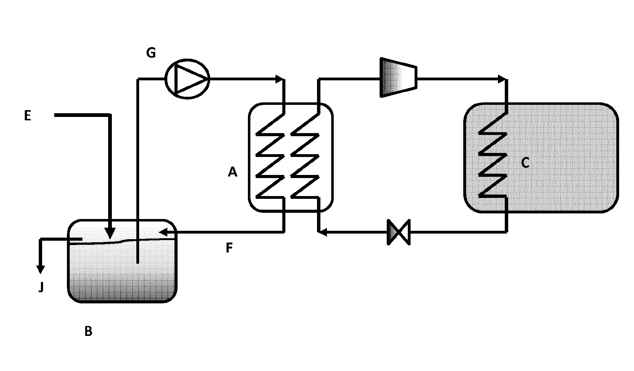
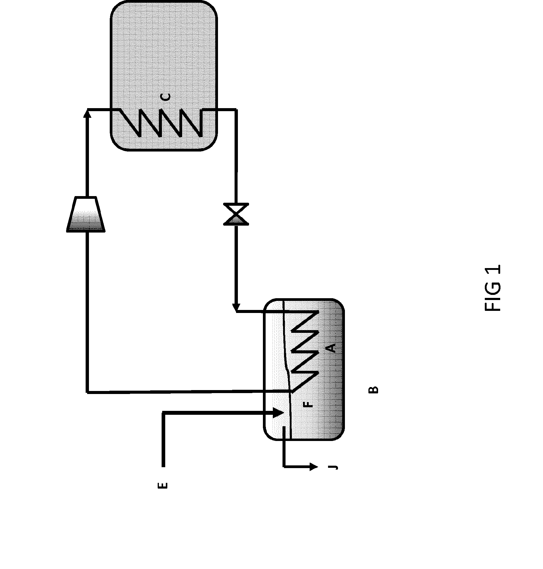
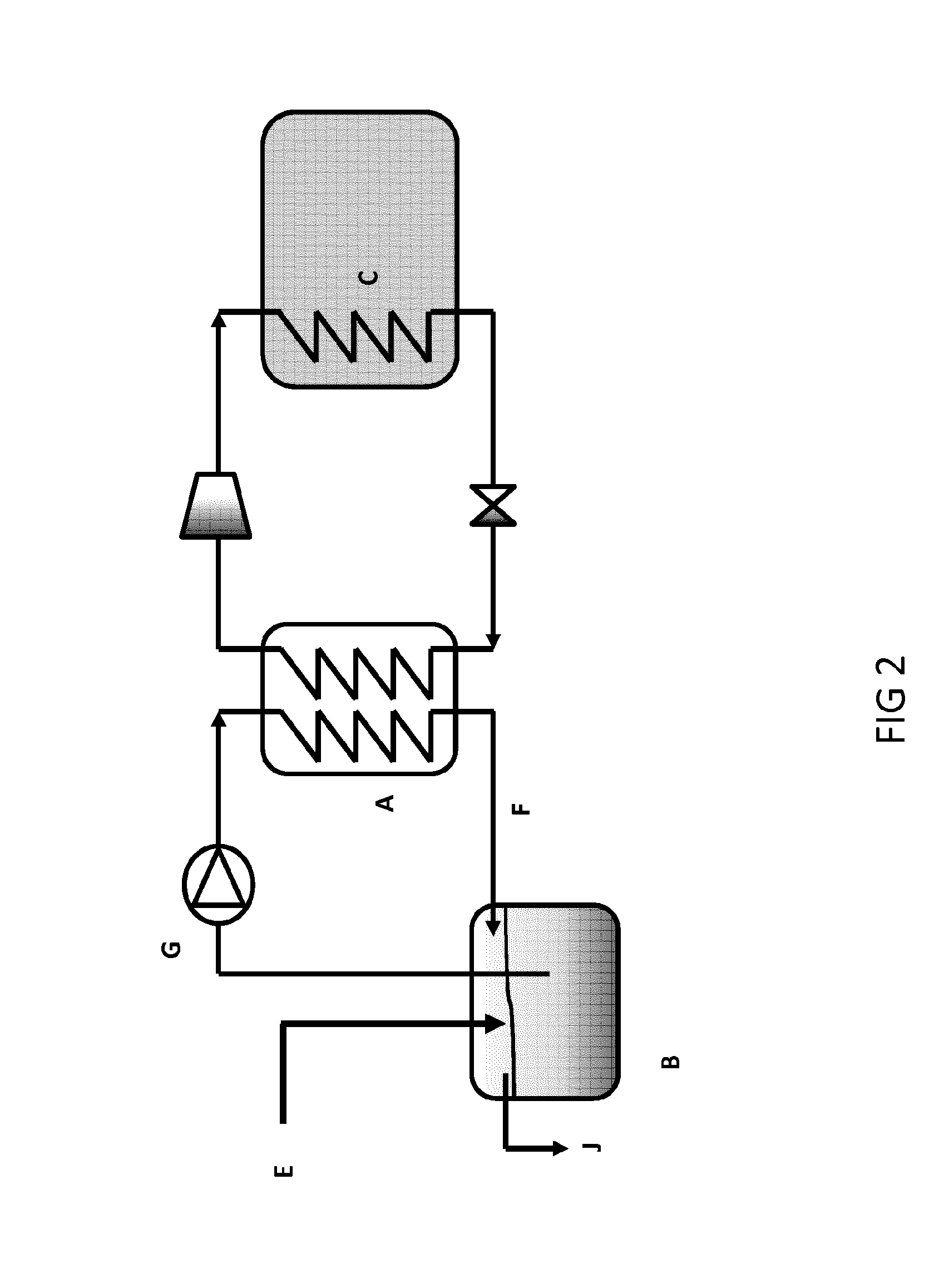
[0029]In a first embodiment in accordance with the present invention and as illustrated in FIG. 1, a heat pump system is provided comprising an heat-exchanger (A) extracting latent heat from liquid stored in a reservoir, thereby forming ice slurry (F), and means for delivering said heat to a heat consumer (C), characterized in that the heat pump system comprises random input of extrinsic liquid (E) into the reservoir (B) and means (J) for removing ice slurry stored in the reservoir outward the system

[0030]In the context of the present invention, random input of extrinsic liquid may be input on regular or irregular,—depending on availability of the extrinsic liquid—, moments in time of any kind of extrinsic liquid, i.e. liquid brought into the reservoir from anywhere outside the heat pump system and containing a certain amount of thermal energy. Examples may be input of collected rainwater, domestic waste water, seawater, process water or fluids from any kind of manufacturing or indu...

example 1

[0064 illustrates the reduced reservoir size of a heat pump system in accordance with the present invention compared to conventional systems:

[0065]An average Belgian house of 150 m2, occupied by 4 residents, isolated conform the current local regulations, exposed to the average Belgian weather conditions requires a reservoir of approximately 20 000-25 000 liters to supply heat for heating the house and for generating domestic hot water. The reservoir is incorporated in the soil requiring a ground level surface of less than a parking place for 1 car.

example 2

[0066 illustrates the application of a heat pump system in accordance with the present invention in urbanized areas:

[0067]The rainwater pit to supply water for the heat pump can be used by several users. The rainwater must then be distributed by a rainwater distribution loop. The rainwater reservoir is installed under the asphalt of the public road and is integrated with the other utility supplies and drain systems. Since the surface to collect rainwater is an important parameter in the design and sizing of the rainwater pit, it is beneficial to use the surface of the public road combined with the surfaces of the roofs of the houses to collect as much as possible rainwater. The system becomes now a public utility system that is explored and maintained by for example a public or private held utility company. It makes the use of heat pumps feasible in densely populated areas, which is almost impossible with the traditional heat pump technology.

[0068]EXAMPLE 3 illustrates the applicati...


PUM


Abstract

A heat pump system is disclosed comprising a heat-exchanger extracting latent heat from liquid stored in a reservoir, thereby forming an ice slurry. The heat pump also includes a device for delivering the heat to a heat consumer. The heat pump system includes a random input of extrinsic liquid into the reservoir and a device for removing ice slurry stored in the reservoir outward the system.

Description

FIELD OF THE INVENTION[0001]The present invention relates to a heat pump system comprising an heat-exchanger extracting latent heat from liquid stored in a reservoir and means for delivering said heat to a heat consumer.BACKGROUND OF THE INVENTION[0002]Heat pumps have the ability to move thermal energy from one environment to another. In general, heat pumps work as follows: the refrigerant, in its gaseous state, is pressurized and circulated through the system by a compressor. On the discharge side of the compressor, the now hot and highly pressurized vapor is cooled in a heat exchanger (preferably a condenser) until it condenses into a high pressure, moderate temperature liquid. The condensed refrigerant then passes through a pressure-lowering device such as an expansion valve. The low pressure, liquid refrigerant leaving the expansion valve enters another heat exchanger (preferably an evaporator), in which the fluid absorbs heat and boils. The refrigerant then returns to the compr...

Claims


Application Information

Patent Timeline
Patent Type & Authority Applications(United States)
IPC IPC(8): F25B30/06F24D19/00F25C1/14
CPCF25B30/06F25C1/14F24D2200/32F24D2200/11F24D2200/13F24D19/00F24D3/18F25B30/02F24D17/001F24D17/02F24D19/0095F28D20/02F24D2200/12F24D2200/20Y02B10/70F25B7/00F25B25/005F25B2339/047F28F19/008F25B29/003F24D10/00F24D2200/24Y02B30/52F28D20/021Y02B10/40F25C2301/002Y02B30/18Y02B30/12Y02B30/17Y02E60/14Y02P60/85
Inventor VAN GYSEL, CARL
Owner VGE
Why Eureka
Try Eureka