Method and apparatus for road width estimation

a road width and estimation method technology, applied in the field of three-dimensional modeling, can solve the problems of time-consuming and costly methods, requiring significant amounts of human measurement and calculation, and resource-intensive 3d modeling methods of road geometry

Inactive Publication Date: 2015-04-30
HERE GLOBAL BV
View PDF7 Cites 41 Cited by
  • Summary
  • Abstract
  • Description
  • Claims
  • Application Information

AI Technical Summary

Benefits of technology

[0015]In another example embodiment, a computer program product is provided, having at least one computer-readable storage medium having computer-executable program code portions stored therein, the computer-executable program code portions comprising program code instructions that, when executed, cause an apparatus to access a point cloud representing terrain. In one such embodiment, the point cloud may be generated from lidar scanning during a trip. The program code instructions, when executed, further cause the apparatus to divide the point cloud into sections representing portions of the terrain, and calculate a road width of each of the sections. The program code instructions, when executed, may further cause the apparatus to apply a smoothing algorithm to adjust the calculated road width of at least one section.

Problems solved by technology

Traditional methods for 3D modeling of road geometry are resource intensive, often requiring significant amounts of human measurement and calculation.
Such methods are thus time consuming and costly.
Exacerbating this issue is the fact that many modern day applications (e.g., 3D mapping, terrain identification, or the like) require the analysis of large amounts of data, and therefore are not practical without quicker or less costly techniques.
Some current methods rely upon 3D light detection and ranging (lidar) data to perform road terrain detection, but these methods have deficiencies.
For instance, some systems designed for terrain detection around a vehicle exist, but are unable to handle cases where the road does not include a curb.
Other techniques appear to use elevation-based road segments, but are also only able to detect road edges where there is a curb.
Moreover, these techniques are unable to handle roads on which there is missing lidar data (occlusions) regarding the road surface.
Finally, these methods may be unable to calculate or estimate road width, at least with a desired accuracy.

Method used


Image

  • Method and apparatus for road width estimation
  • Method and apparatus for road width estimation
  • Method and apparatus for road width estimation

Examples


Embodiment Construction

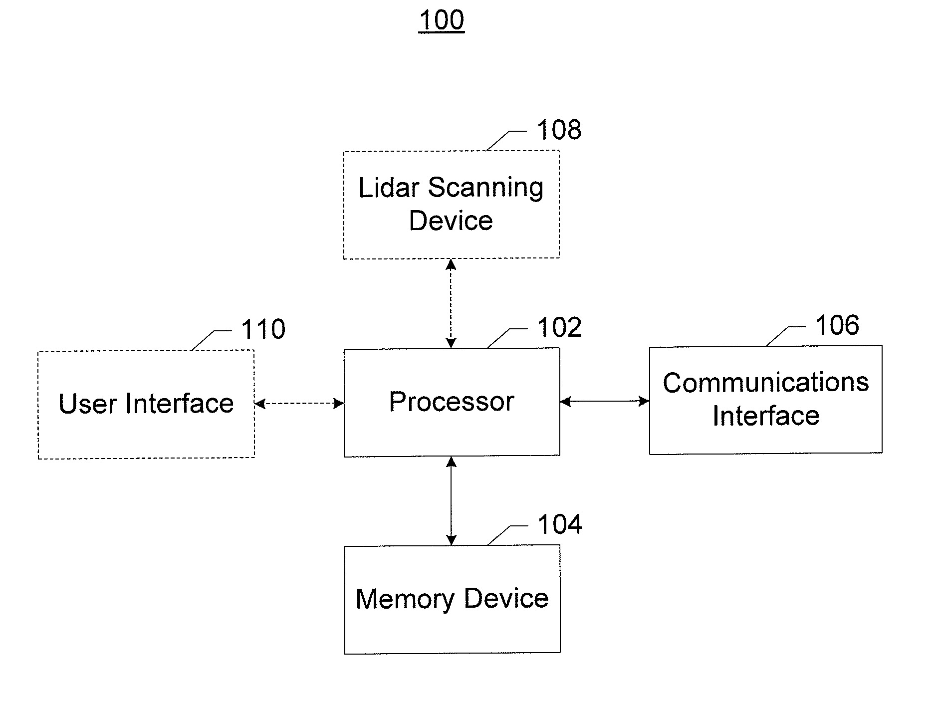
[0037]Some embodiments of the present invention will now be described more fully hereinafter with reference to the accompanying drawings, in which some, but not all embodiments of the inventions are shown. Indeed, these inventions may be embodied in many different forms and should not be construed as limited to the embodiments set forth herein; rather, these embodiments are provided so that this disclosure will satisfy applicable legal requirements. Like numbers refer to like elements throughout. As used herein, the terms “data,”“content,”“information,” and similar terms may be used interchangeably to refer to data capable of being transmitted, received, and / or stored in accordance with embodiments of the present invention. Thus, use of any such terms should not be taken to limit the spirit and scope of embodiments of the present invention.

[0038]Additionally, as used herein, the term “circuitry” refers to (a) hardware-only circuit implementations (e.g., implementations in analog cir...


PUM


Abstract

A method, apparatus, and computer program product are disclosed to estimate road widths, irrespective of the presence of curbs or occlusions on the road surface. In the context of a method, a point cloud representing terrain is accessed. In one embodiment, the point cloud may be generated from lidar scanning during a trip. The point cloud is divided into sections representing portions of the terrain. The method further includes, for each section, identifying a ground planar surface of the section, estimating a drive plane of the section based on the ground planar surface and a drive direction, and calculating a road width of the section based on the ground planar surface and drive plane. The method may further include applying a smoothing algorithm to adjust the calculated road width of at least one section. A corresponding apparatus and computer program product are also provided.

Description

TECHNOLOGICAL FIELD[0001]Example embodiments of the present invention relate generally to three dimensional modeling and, more particularly, to a method and apparatus for estimating road geometry.BACKGROUND[0002]Road geometry modeling is very useful for three dimensional (3D) map creation and 3D terrain identification. Traditional methods for 3D modeling of road geometry are resource intensive, often requiring significant amounts of human measurement and calculation. Such methods are thus time consuming and costly. Exacerbating this issue is the fact that many modern day applications (e.g., 3D mapping, terrain identification, or the like) require the analysis of large amounts of data, and therefore are not practical without quicker or less costly techniques.[0003]Some current methods rely upon 3D light detection and ranging (lidar) data to perform road terrain detection, but these methods have deficiencies. For instance, some systems designed for terrain detection around a vehicle e...

Claims


Application Information

Patent Timeline
Patent Type & Authority Applications(United States)
IPC IPC(8): G01S17/89G01B11/02
CPCG01B11/02G01S17/89G01C15/00G01C21/3602G01S7/4808G06T7/60G06T2207/10028G06T2207/20021G06T2207/30252G06T7/75G06V20/588
Inventor MA, XIANGCHEN, XIN
Owner HERE GLOBAL BV
Why Eureka
Try Eureka