
Orbital Angular Momentum

a technology of orbital angular momentum and electromagnetic field, which is applied in the direction of optical elements, optical radiation measurement, instruments, etc., can solve the problems of inability to integrate, inconvenient operation, and inability to generate light carrying oam using bulk optics

Active Publication Date: 2015-05-07
PSIQUANTUM CORP
View PDF3 Cites 20 Cited by
  • Summary
  • Abstract
  • Description
  • Claims
  • Application Information

AI Technical Summary

Benefits of technology

The patent text is about a way to efficiently transfer electromagnetic waves into a closed-loop waveguide from a nearby input waveguide. This is done by using evanescent coupling, which is maximised by making the coupling point between the resonator and the input waveguide critical. The technical effect is a more efficient transfer of electromagnetic waves, allowing for better control and manipulation of the waveform.

Problems solved by technology

Current techniques for generating light carrying OAM using bulk optics, including computer generated holograms, spiral phase plates, q-plates and dove prisms, have limitations in terms of efficiency, cost, flexibility and scalability.
These methods do not lend themselves to integration which is essential for widespread and large scale utilization in future applications.

Method used


Image

  • Orbital Angular Momentum
  • Orbital Angular Momentum
  • Orbital Angular Momentum

Examples


Embodiment Construction

)

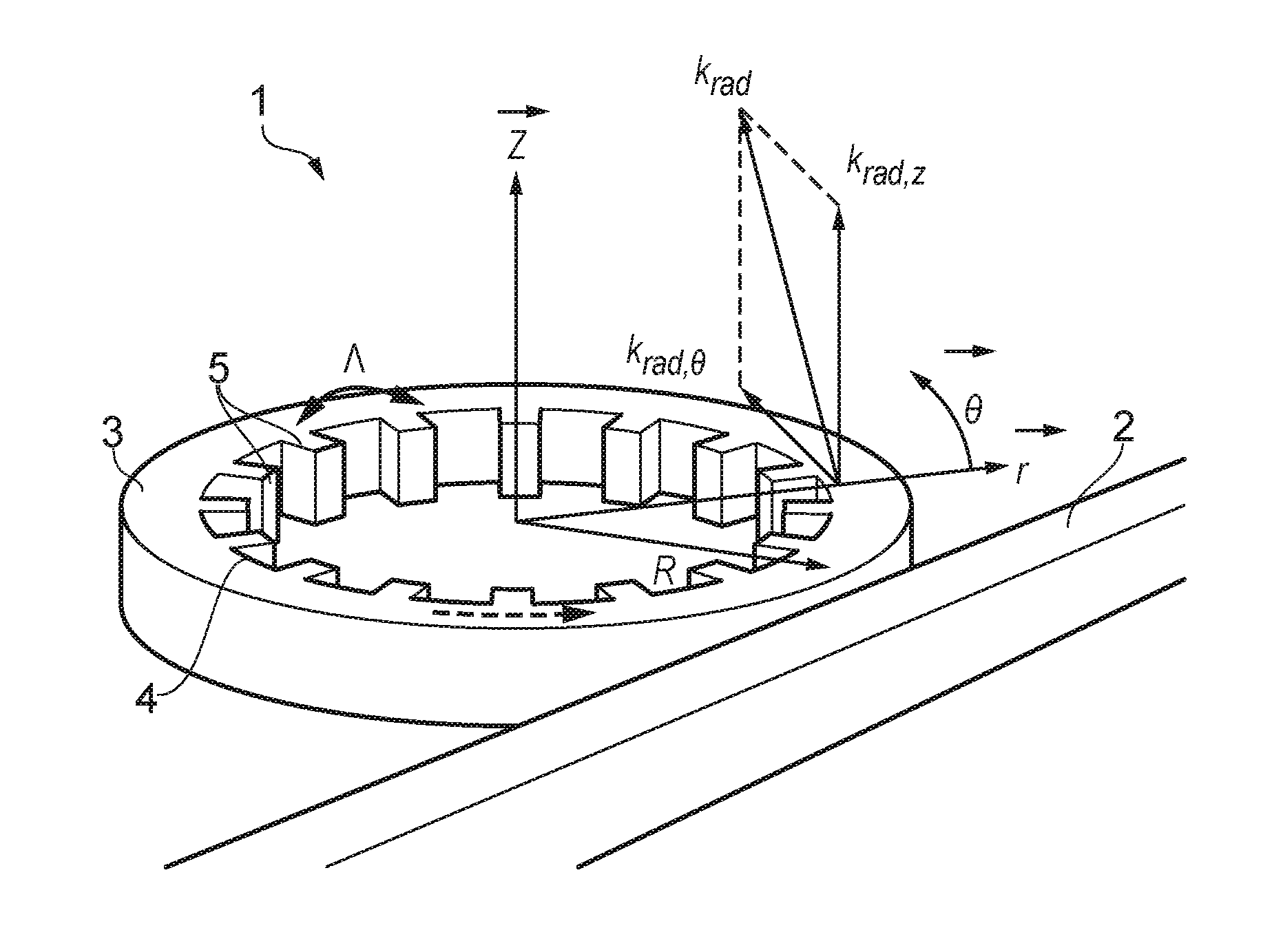
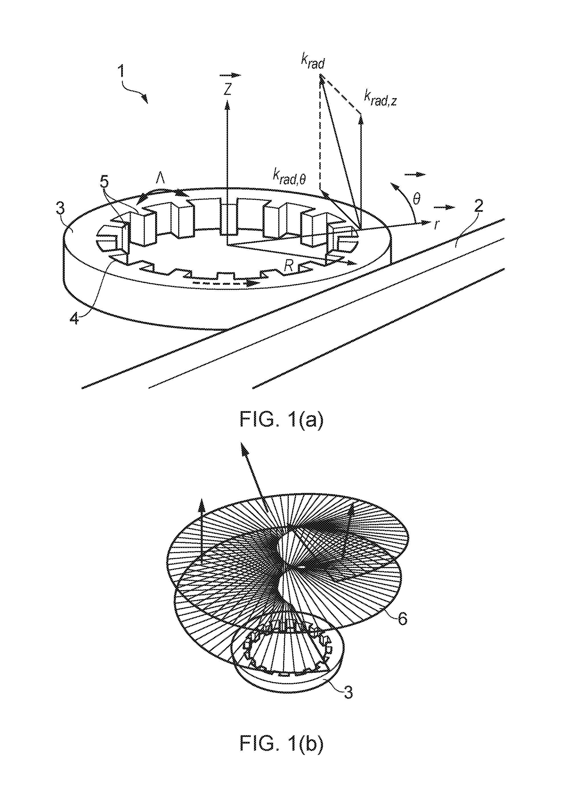
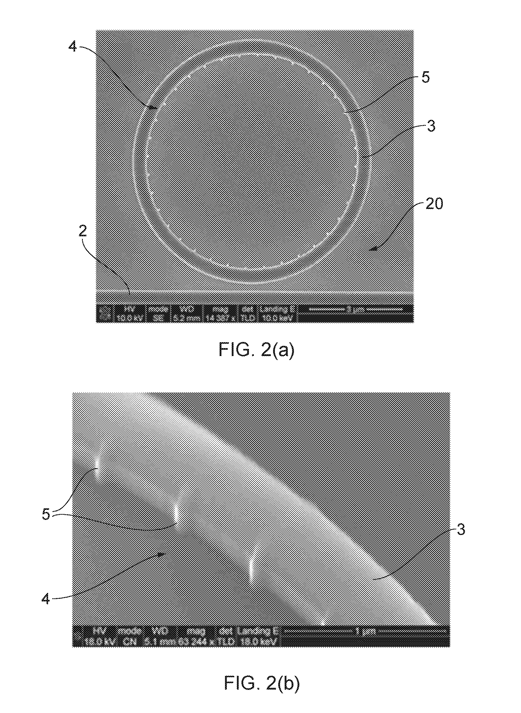
[0075]FIG. 1 (a) illustrates an optical resonator 1 including an input straight (linear) waveguide 2 and a closed-loop ring waveguide 3. An angular grating 4 is patterned within the ring waveguide 3. The angular grating is used to selectively couple a guided wave propagating in the ring waveguide with an in-plane angular wave vector to a free space radiation mode with a wave vector pointing at an angle from the waveguide plane.

[0076]The ring waveguide 3 is an example of a substantially planar waveguide structure that provides strong confinement of light that propagates around the ring by way of total internal reflection. At one or more resonant wavelengths of the ring waveguide 3 constructive interference occurs which develops the intensity of the guided wave propagating in the waveguide as it executes multiple circuits of the ring. Light is coupled into the ring waveguide 3 evanescently from the input waveguide 2. Efficient coupling from the input waveguide to the ring waveguide 3...


PUM


Abstract

The invention relates to methods, devices, systems and uses of such systems for the generation and detection of electromagnetic fields carrying orbital angular momentum. An electromagnetic wave placed in a resonator having a closed-loop waveguide supporting a guided wave propagating at resonance with angular order, p, and with an angular grating patterned in the closed-loop waveguide, the angular grating having a integer number, q, of grating elements. The angular grating selectively couples the guided wave mode to a free space radiation mode having an OAM quantity, l, and out-of-plane wave vector component, krad,z, and wherein significant coupling to the grating occurs only when the following wave matching condition is satisfied: l=p−mq where: m is the diffraction order of the angular grating, m=1, 2, 3, . . . ,.

Description

FIELD OF THE INVENTION[0001]The present invention relates to the generation and detection of electromagnetic fields carrying orbital angular momentum. In particular, the invention relates to methods, devices, systems and uses of such systems for the generation and detection of electromagnetic fields carrying orbital angular momentum.BACKGROUND OF THE INVENTION[0002]An electromagnetic field, and indeed a single photon, carries energy and momentum. The momentum may comprise two components. Linear momentum is responsible for the observable radiation pressure, whilst angular momentum is the rotation of the wave around its own axis as it propagates forward and is observable as a radiation torque. The angular momentum also comprises two components, namely spin angular momentum and orbital angular momentum (OAM). For a paraxial beam spin angular momentum is associated with polarization, whilst OAM is associated with the spatial field distribution.[0003]Of particular interest is the origin ...

Claims


Application Information

Patent Timeline
IPC IPC(8): G02B6/124
CPCG02B6/124G02B6/12007G02B6/12
Inventor YU, SIYUANTHOMPSON, MARKCAI, XINLUN
Owner PSIQUANTUM CORP
Learn More