Magnetically shielded miniature hall thruster

a hall thruster and magnet shielding technology, applied in the field of hall thrusters, can solve the problems of low electron temperature at the discharge channel wall, high erosion rate, and potential for longer thruster life, and achieve the effect of reducing the radial electric field component, eliminating the effect of ion bombardment erosion of the thruster channel wall, and prolonging the thruster li

Inactive Publication Date: 2015-05-14
RGT UNIV OF CALIFORNIA
View PDF4 Cites 26 Cited by
  • Summary
  • Abstract
  • Description
  • Claims
  • Application Information

AI Technical Summary

Benefits of technology

[0011]A magnetically shielded miniature (MaSMi) Hall thruster according to an embodiment of the technology described herein is a miniaturized Hall effect thruster that employs a unique magnetic field geometry called “magnetic shielding.” This field topography prevents the intersection of the grazing magnetic field line (the line coming closest to the discharge channel wall) with the discharge channel. Instead, the grazing field line penetrates into the anode region of the thruster, accessing cold electrons and holding them near the channel walls. A significant reduction in the wall sheath potential and a plasma potential nearly equal to the discharge voltage near the walls result from the unique field topography, yielding a significant reduction in the radial electric field component along the channel that would normally accelerate nearby ions into the channel walls. This virtually eliminates the effects of ion bombardment erosion of the thruster channel walls, which is the primary failure mechanism in conventional Hall thrusters. The use of magnetic shielding has demonstrated significantly longer thruster lifetimes when used in 4+ kW Hall thrusters.
[0012]A unique feature according to some embodiments of the current disclosure is the utilization of the magnetic shielding to improve the efficiency of small Hall thrusters. Magnetic shielding has demonstrated the potential for longer thruster life in standard size (>4 kW) Hall thrusters to date, but not improvements in efficiency. The increased plasma-wall interactions common to low-power Hall thrusters results in greater high-energy electron losses to the wall, yielding increased operating temperatures and poorer efficiency (typically <40%). By properly designing magnetic shielding geometries specifically for small Hall thrusters, we can greatly reduce the power deposition to the walls and enable small Hall thrusters to operate with unprecedented high total efficiencies (at least by 30% and possibly ≧50%).
[0013]The small size of the device allows for a variety of spacecraft applications. The MaSMi Hall thruster may be used as a primary method of propulsion for small-satellites (i.e. CubeSats and SmallSats) designed for long-duration missions. This thruster is also capable of delivering precise applications of low thrust, makin

Problems solved by technology

This unique field topology results in low electron temperature at the discharge channel walls while eliminating strong electric field components that would otherwise lead to high erosion rates from ion acceleration into the channel walls.
Magnetic shielding has demonstrated the potential for longer thruste

Method used


Image

  • Magnetically shielded miniature hall thruster
  • Magnetically shielded miniature hall thruster
  • Magnetically shielded miniature hall thruster

Examples


Embodiment Construction

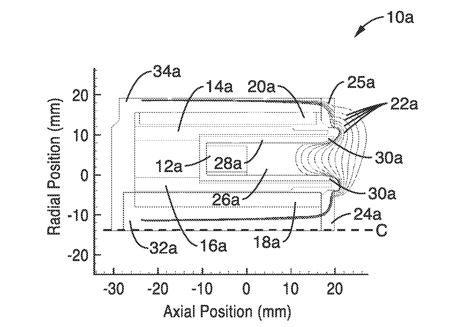
[0039]The primary life-limiting factor of conventional Hall thrusters is erosion of the discharge channel walls from ion bombardment. Due to the zero net current condition at the insulating walls, a large sheath potential forms to reject the bulk of the electron population. In turn, the electron repelling sheath adds to the radial electric field component from the bulk plasma that accelerate nearby ions into the walls. The resultant sputter erosion of the wall is concentrated near the exit plane and can wear through the discharge channel walls, exposing the thruster's pole pieces to ion bombardment. Degradation of the pole pieces alters the interior magnetic circuit of the device, eventually degrading the performance of the thruster and ending its useful life.

[0040]Another key performance-limiting factor in Hall thrusters is high-energy electron power loss to the discharge channel walls. In conventional Hall thrusters, the radial magnetic field lines near the exit plane intersect th...


PUM


Abstract

Magnetically shielded miniature Hall thrusters are disclosed that use a unique magnetic field topology that prevents the magnetic field lines from intersecting the discharge channel walls in the acceleration region of the thruster. Instead, the lines of force originating from both the inner and outer pole pieces curve around the downstream edges of the discharge channel and follow the channel walls towards the anode. This unique field topology results in low electron temperature at the discharge channel walls while eliminating strong electric field components that would otherwise lead to high erosion rates and power deposition from ion acceleration into the channel walls.

Description

CROSS-REFERENCE TO RELATED APPLICATIONS[0001]This application claims priority to, and the benefit of, U.S. provisional patent application Ser. No. 61 / 887,220 filed on Oct. 4, 2013, incorporated herein by reference in its entirety.STATEMENT REGARDING FEDERALLY SPONSORED RESEARCH OR DEVELOPMENT[0002]Not ApplicableINCORPORATION-BY-REFERENCE OF COMPUTER PROGRAM APPENDIX[0003]Not ApplicableNOTICE OF MATERIAL SUBJECT TO COPYRIGHT PROTECTION[0004]Not ApplicableBACKGROUND[0005]1. Technical Field[0006]This disclosure pertains generally to Hall thrusters, and more particularly to miniature Hall thrusters.[0007]2. Background Discussion[0008]A long-life, low-power Hall thruster would be attractive for a wide range of NASA missions. Such a thruster would provide deep space and near Earth mission planners with the combined advantages of high specific impulse (>1500 s) and high thrust-to-power ratio (>50 mN / kW) at a reduced scale. Numerous miniature Hall thrusters have been developed in an e...

Claims


Application Information

Patent Timeline
IPC IPC(8): F03H1/00
CPCF03H1/0068F03H1/0075
Inventor CONVERSANO, RYAN W.GOEBEL, DAN M.WIRZ, RICHARD E.
Owner RGT UNIV OF CALIFORNIA
Why Eureka
Try Eureka