Plasma generation device and plasma processing device

Active Publication Date: 2011-05-19
ELECTRO-MOTIVE DIESEL +1
View PDF18 Cites 21 Cited by
  • Summary
  • Abstract
  • Description
  • Claims
  • Application Information

AI Technical Summary

Benefits of technology

[0026]The present invention makes it possible to obtain a plasma generation device using a radio-frequency antenna that is simple in structure and hence easy to manufacture as well as easy to attach, remove, maintain and inspect, and also a plasma processing device using such a plasma generation dev

Problems solved by technology

In recent years, plate electrodes have been extremely large to cope with the rapid increase in the size of glass substrates for display devices, causing a non-negligible degree of wavelength effect of the applied radio-frequency voltage.
However, it has a problem due to the use of the dielectric plasma chamber: The dielectric container needs to be made of quartz glass, alumina or similar materials, which are rather low in mechanical strength and hence easy to be broken and hard to handle.
This unfavorable characteristic also impedes the creation of large devices.
When, in this case, the radio-frequency current varies, the potential d

Method used


Image

  • Plasma generation device and plasma processing device
  • Plasma generation device and plasma processing device
  • Plasma generation device and plasma processing device

Examples


first embodiment

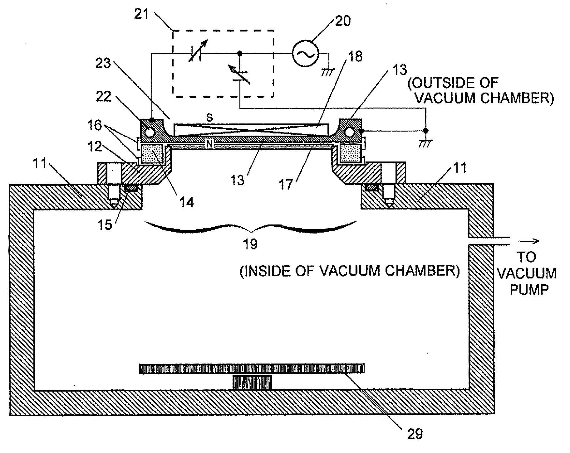
[0052]A plasma generation device of the first embodiment is hereinafter detailed with reference to FIG. 1. The radio-frequency antenna conductor 13 is a rectangular aluminum plate that approximately measures 60 mm in width and 120 mm in length. The vacuum-facing side of the radio-frequency antenna conductor 13 is flat, whereas the air-facing side has a hollow portion 23, in which the magnetic generation device 18 is placed. The radio-frequency antenna conductor 13 is thicker at its circumference than at the hollow portion 23. A water channel 22 for circulating cooling water is formed in the thicker portion of the conductor. In the present embodiment, the hollow portion 23 has a thickness of approximately 3 mm so as to enable a magnetic field to pass through the radio-frequency antenna conductor 13 and the dielectric shield plate 17 to the vacuum-facing side. Obviously, the thickness of the radio-frequency antenna conductor 13 is not limited to this value; it should be changed accord...

second embodiment

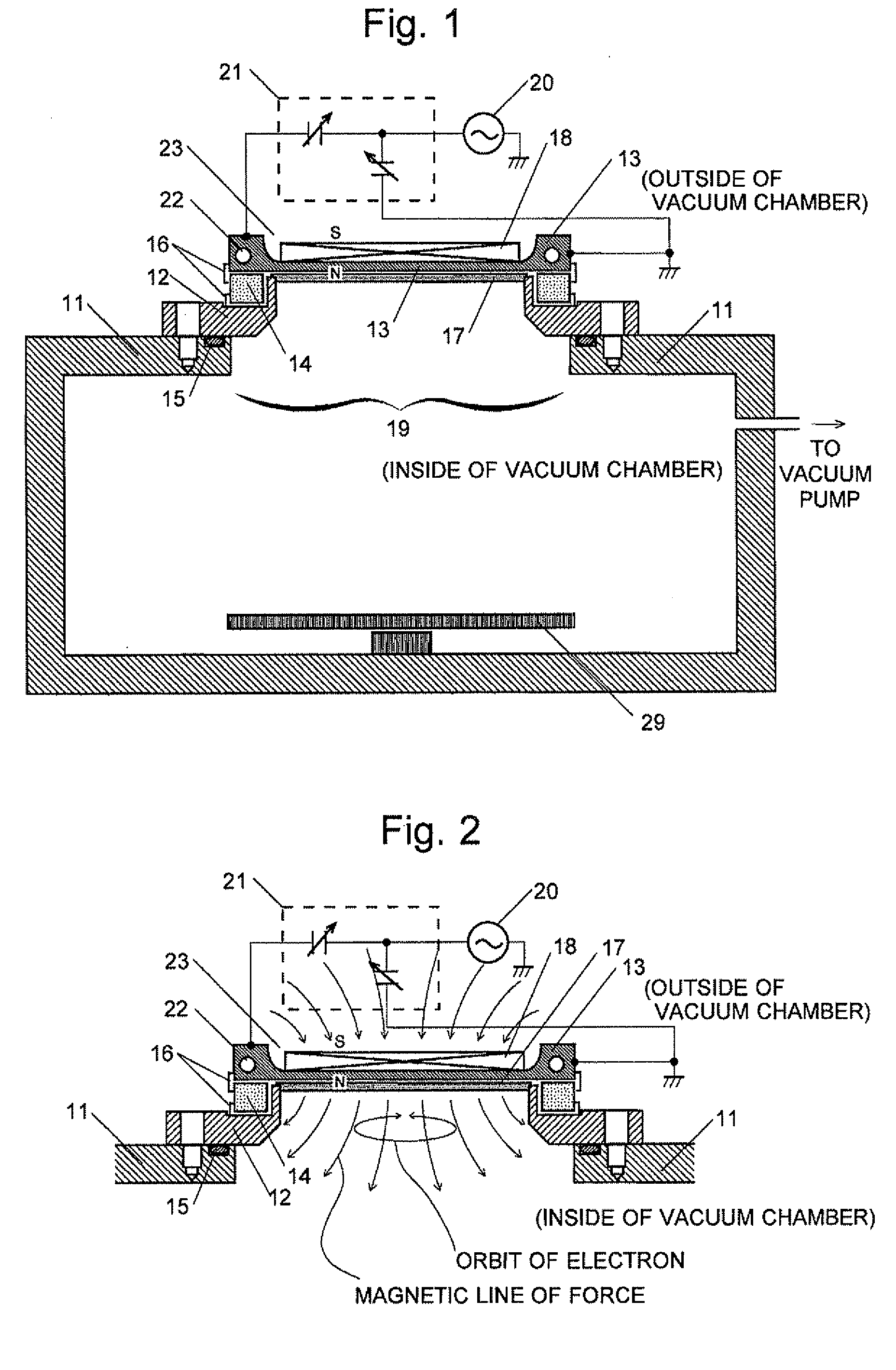
[0062]Regarding the configuration of the radio-frequency antenna and nearby components in a plasma generation device of the second embodiment, a schematic sectional view of the main components is shown in FIG. 3. The plasma generation device of the present embodiment has basically the same configuration as that of the first embodiment except for the radio-frequency antenna conductor 33 and the wiring for supplying power to the radio-frequency antenna conductor 33. The radio-frequency antenna conductor 33 has a length that approximately doubles the length of the radio-frequency antenna conductor 13 of the first embodiment. Furthermore, a projection 30 for supplying radio-frequency power is provided at its center, and both ends are connected to ground. A radio-frequency power is supplied via the matching box to the projection 30 so that radio-frequency current flows from the center to the two ends connected to ground.

[0063]According to the present embodiment, it is possible to approxi...

third embodiment

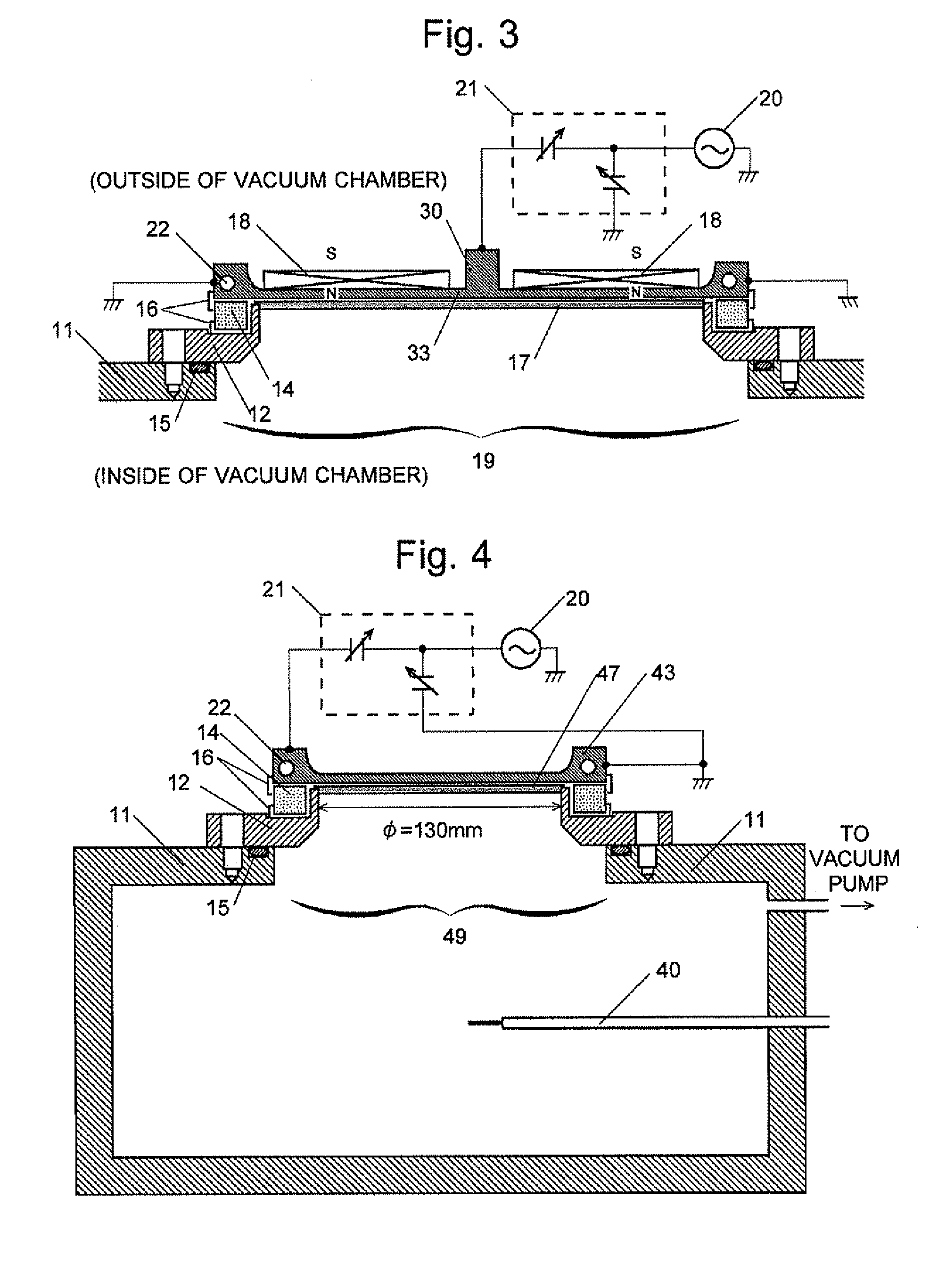
[0065]Regarding the configuration of the radio-frequency antenna and nearby components in a plasma generation device of the third embodiment, a schematic sectional view of the main components is shown in FIG. 4. The present embodiment has basically the same configuration as that of the first embodiment except for the use of a radio-frequency antenna conductor 43, which consists of an aluminum disc having a diameter of 180 mm (with a plasma generation area having a diameter of 130 mm). It should also be noted that the magnetic field generator used in the first embodiment is not used in the present embodiment. For consistency with the shape of the radio-frequency antenna conductor 43, the insulating frame 44 is transformed from the first embodiment to a ring-like circular shape, the dielectric shield plate 47 to a disc shape, and the opening 49 to a circular shape. A radio-frequency power source (frequency: 13.56 MHz) is connected via a matching box to a point (power supply point) on ...


PUM


Abstract

A flange, which forms a portion of a vacuum container, has a rectangular opening surrounded by an insulating frame. A plate-shaped radio-frequency antenna conductor 13 is provided so as to cover the opening, with the insulating frame clamped thereby. In this structure, a radio-frequency power source is connected via a matching box to one end along the length of the radio-frequency antenna conductor, the other end is connected to ground, and electric power is supplied so that a radio-frequency current flows from one end of the radio-frequency antenna conductor to the other. By this method, the impedance of the radio-frequency antenna conductor can be lowered, and high-density plasma with a low electron temperature can be efficiently generated.

Description

TECHNICAL FIELD[0001]The present invention relates to a device for generating plasma, and also a plasma processing device for etching a substrate surface or producing a thin film by using plasma generated by the aforementioned device.BACKGROUND ART[0002]Plasma processing devices, such as plasma CVD (chemical vapor deposition) devices, dry-etching devices or ashing devices, are generally used in the process of producing semiconductor devices, liquid crystal displays, solar cells or other devices. In these devices, generation of high-density plasma covering a large area with a high level of uniformity is required for various purposes, such as dealing with large substrates, increasing the processing rate, and creating fine patterns. A plasma generation technique that is generally used for those purposes is a parallel-plate system. The parallel-plate system uses a pair of plate electrodes disposed parallel to each other in a vacuum container and generates plasma between them by applying...

Claims


Application Information

Patent Timeline
IPC IPC(8): H05H1/46H05H1/24
CPCH01J37/32091H01J37/321H01J37/32183H01J37/32174H05H1/46H01J37/3211H01J37/3266
Inventor EBE, AKINORIANDO, YASUNORIWATANABE, MASANORI
Owner ELECTRO-MOTIVE DIESEL
Why Eureka
Try Eureka