
Ion generator and ion generating method

a generator and ion generating technology, applied in the direction of measuring devices, electric discharge tubes, instruments, etc., can solve the problems of impurity ions contaminating the wafer, insulation failure, wear of carbon, etc., and achieve the effect of reducing contamination by heavy metal ions and high productivity

Active Publication Date: 2015-05-14
SUMITOMO HEAVY IND ION TECH
View PDF1 Cites 9 Cited by
  • Summary
  • Abstract
  • Description
  • Claims
  • Application Information

AI Technical Summary

Benefits of technology

The present invention provides a solution to reduce heavy metal contamination during ion implantation and generate commercially viable ions.

Problems solved by technology

This might result in that the metal material for the inner wall of the arc chamber is implanted as ions into a semiconductor wafer, leading to contamination of the wafer by impurity ions of the metal or the like.
However, highly reactive radicals, originated from the halide generated in the ionization step, easily cause wear of carbon.
Further, when the carbon ions and neutrals having scattered are deposited onto arc chamber and beam extraction parts and becomes a conductive film, it brings about an insulation failure.
Therefore, life of the ion source becomes significantly short, and the productivity of the implanter deteriorates.

Method used


Image

  • Ion generator and ion generating method
  • Ion generator and ion generating method
  • Ion generator and ion generating method

Examples


Embodiment Construction

[0019]The invention will now be described by reference to the preferred embodiments. This does not intend to limit the scope of the present invention, but to exemplify the invention.

[0020]Hereinafter, the mode for carrying out the present invention will be described in detail with reference to the drawings. It is to be noted that the same element is provided with the same numeral in descriptions of the drawings , and a repeated description is omitted as appropriate. Further, a configuration described below is illustrative and is not to restrict the scope of the present invention.

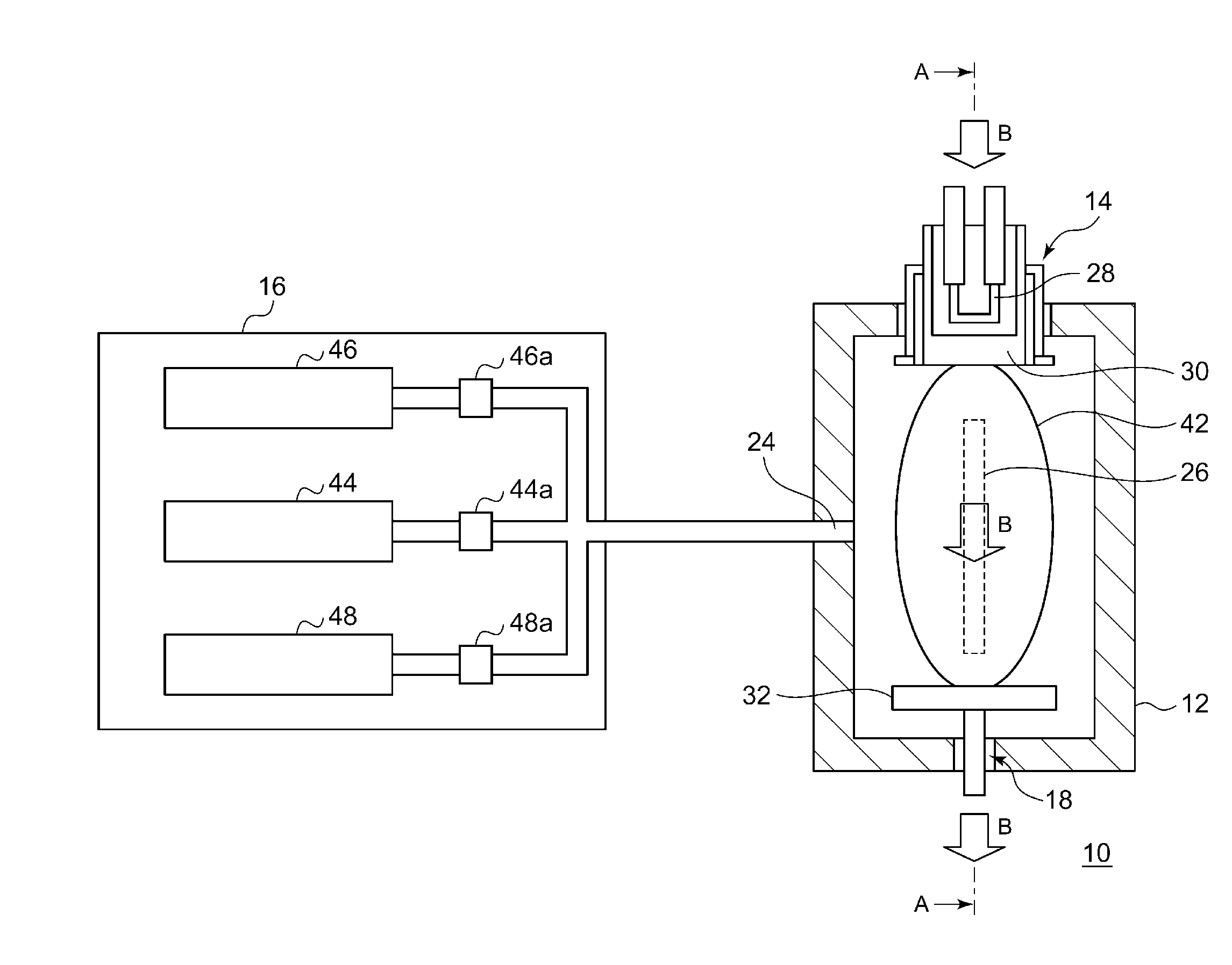
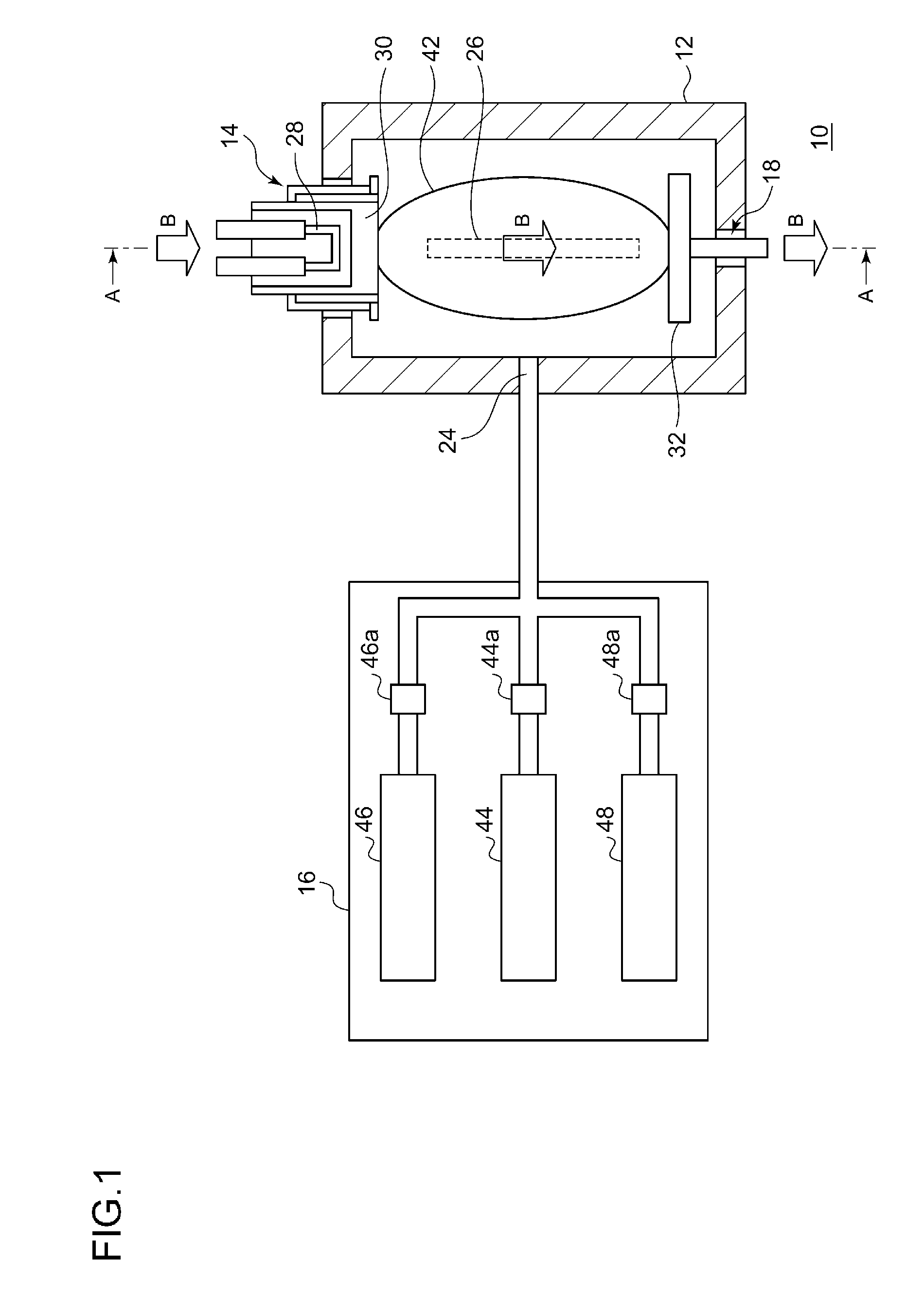
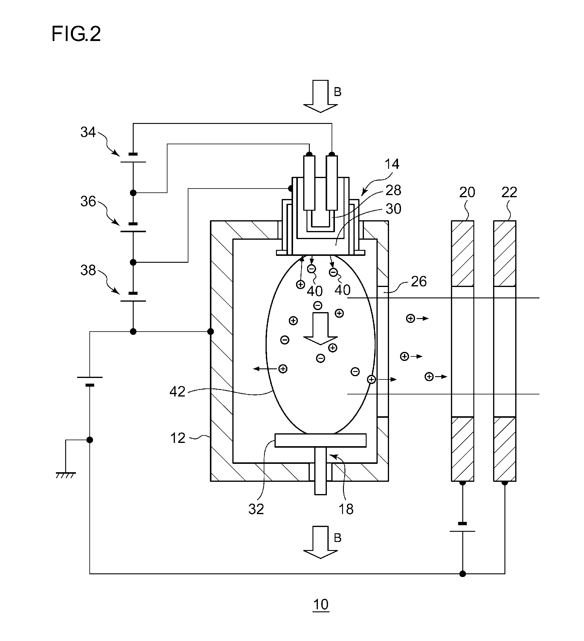
[0021]FIG. 1 is a schematic diagram showing a gas box and the inside of an arc chamber of an ion source according to the present embodiment. FIG. 2 is a schematic diagram showing an A-A cross section of the ion source shown in FIG. 1.

[0022]An ion generator 10 according to the present embodiment is a DC-discharge type ion source, and provided with an arc chamber 12, a thermal electron emitter 14, a repeller 1...


PUM


Abstract

An ion generator is provided with: an arc chamber that is at least partially made up of a material containing carbon; a thermal electron emitter that emits thermal electrons into the arc chamber; and a gas introducer that introduces a source gas and a compound gas into the arc chamber. The source gas to be introduced into the arc chamber contains a halide gas, and the compound gas to be introduced into the arc chamber contains a compound having carbon atoms and hydrogen atoms.

Description

BACKGROUND OF THE INVENTION[0001]1. Field of the Invention[0002]The present invention relates to an ion generator and an ion generating method.[0003]2. Description of the Related Art[0004]In a semiconductor manufacturing process, a process of implanting ions into a semiconductor wafer has been implemented on a standard basis for the purpose of changing conductivity, for the purpose of changing a crystal structure of the semiconductor wafer, and for some other purpose. An apparatus used in this process is generally called an ion implanter.[0005]As an ion source in such an ion implanter, a direct current (DC)-discharge type ion source is known. A DC-discharge type ion source heats a filament by a DC current to generate thermal electrons, and a cathode is heated by the thermal electrons. Then, thermal electrons emitted from the heated cathode are accelerated into an arc chamber and collided with source gas molecules introduced thereinto, to ionize atoms contained in the source gas mole...

Claims


Application Information

Patent Timeline
IPC IPC(8): H01J27/08H01J37/317
CPCH01J27/08H01J2237/31705H01J37/3171H01J37/08
Inventor SATO, MASATERU
Owner SUMITOMO HEAVY IND ION TECH
Learn More