Electric motor

a technology of electric motors and motors, applied in the direction of mechanical energy handling, magnetic circuit rotating parts, shape/form/construction, etc., can solve the problems of ineffective space generation, unstable position and a state of coils, and possible rotation imbalance of armatures, so as to reduce the size of the deformed slot, reduce the size, and suppress the generation of ineffective spa

Active Publication Date: 2015-05-14
MITSUBA CORP
View PDF7 Cites 16 Cited by
  • Summary
  • Abstract
  • Description
  • Claims
  • Application Information

AI Technical Summary

Benefits of technology

[0027]According to the above-mentioned electric motor, since the first flat section is formed at the cylindrical section of the yoke, the electric motor can be reduced in size in comparison with the case in which the cylindrical section is formed in a cylindrical shape. In addition, as the permanent magnets are disposed at positions distant from the first flat section, the electric motor can be reduced in size regardless of the thickness of the permanent magnet.
[0028]According to the above-mentioned electric motor, the teeth can be tilted in response to the position of the coil wound in each of the deformed slots, and generation of an ineffective space in the deformed slot can be suppressed. For this reason, a space factor of the coil can be improved, and the coil can be distributed in the deformed slots with good balance. As a result, the electric motor can be reduced in size and weight.
[0029]In addition, since the armature core is formed in the deformed shape and in a point-symmetrical shape about the rotary shaft, occurrence of the rotation imbalance of the armature can be more securely prevented.
[0030]According to the above-mentioned electric motor, as the winding method of the winding on the armature core, a so-called double flyer method of winding the winding simultaneously at two places with a relationship in which the distributed winding is point-symmetrical about the rotary shaft can be employed. For this reason, a total time of a winding time of the coil on the armature and a connecting time of the connecting wire to the segments can be further reduced, and manufacturing cost can be further reduced.
[0031]In addition, since a positional relationship between the predetermined segments and the predetermined teeth through which the winding crosses is an opposite positional relationship about the rotary shaft, the winding under the commutator can be routed to be hooked by the rotary shaft. For this reason, it is possible to prevent the winding under the commutator from being loosened outward in the radial direction, and it is possible to reduce thickening due to the winding.

Problems solved by technology

For this reason, when all of the slots are formed in the same shape, an ineffective space is generated at each of the slots, and a position and a state of the coil become unstable.
As a result, rotation imbalance of the armature may occur.

Method used


Image

  • Electric motor
  • Electric motor
  • Electric motor

Examples


first embodiment

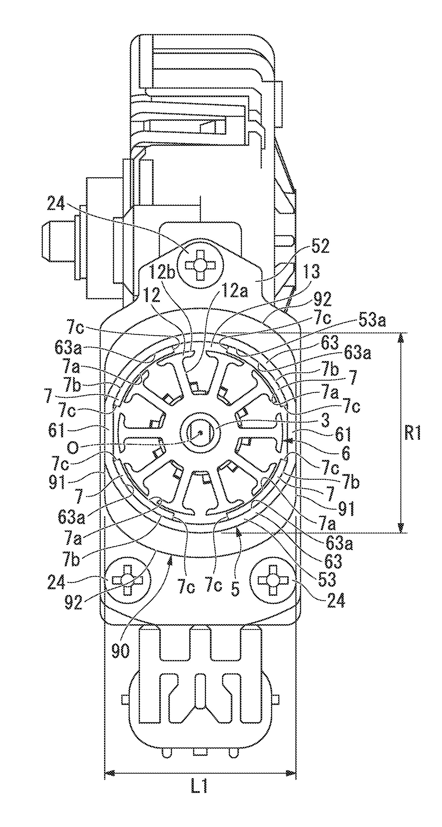
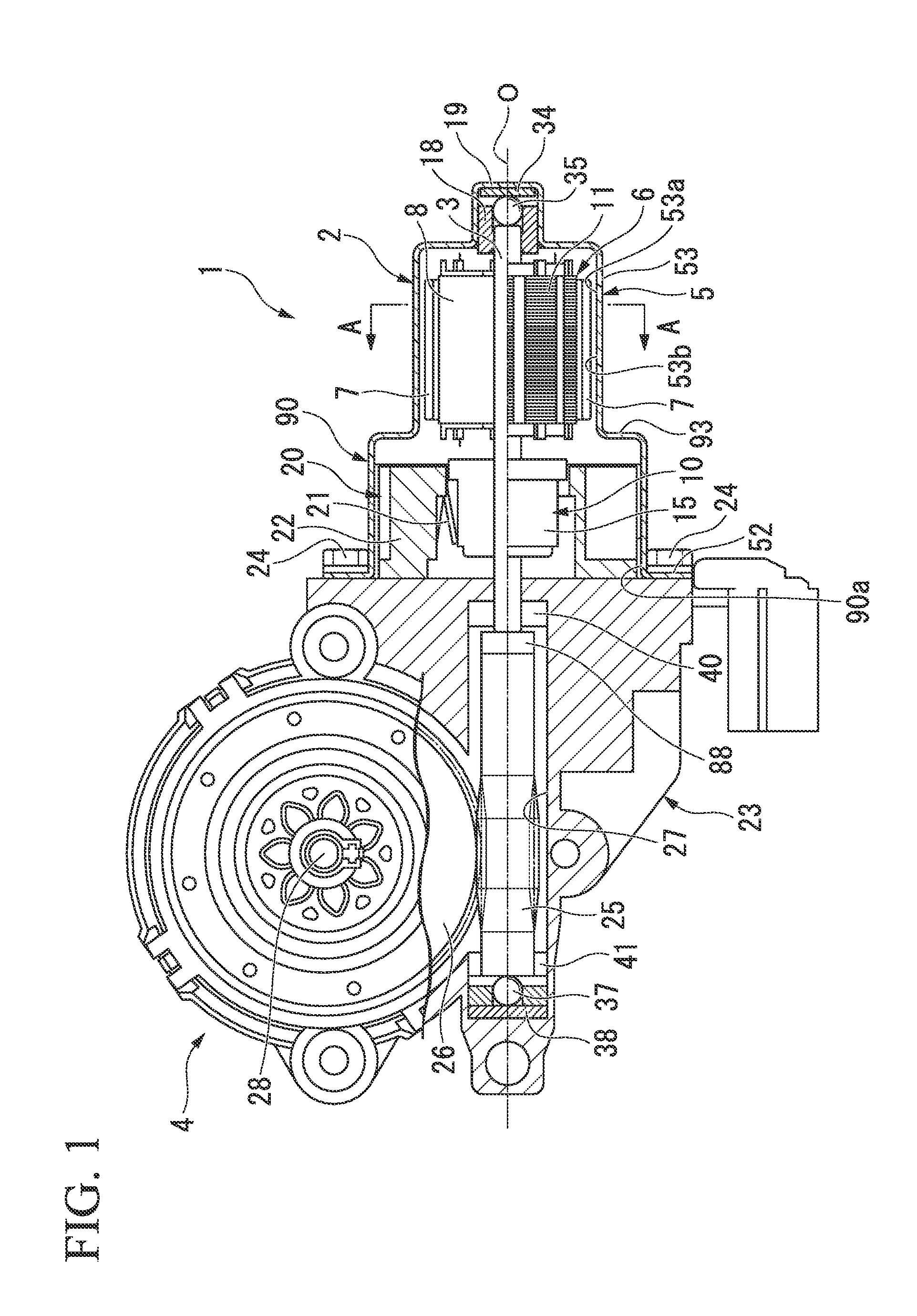
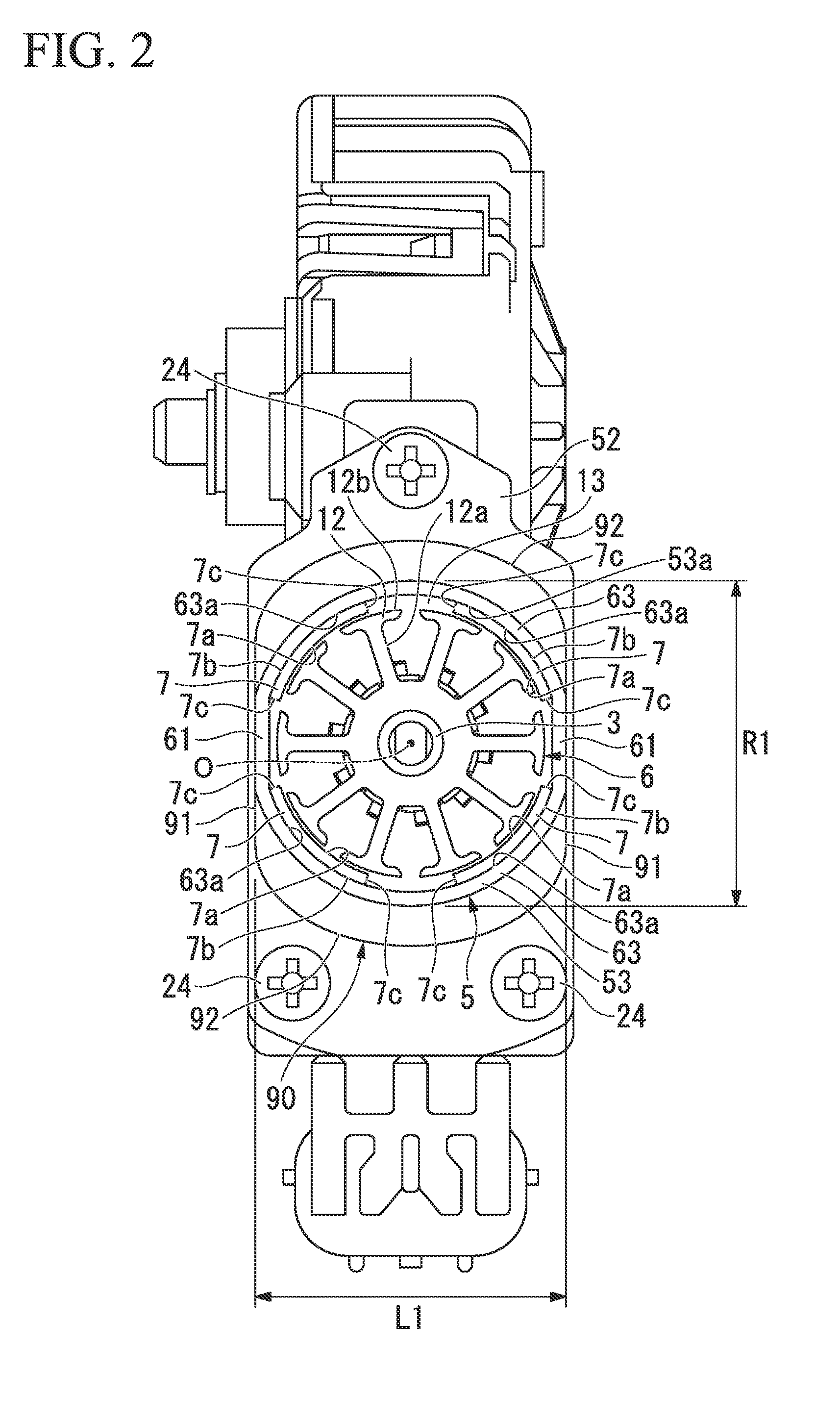
[0060]Hereinafter, an electric motor 2 of a first embodiment and a speed-reduction-mechanism-attached motor apparatus 1 (corresponding to “a driving apparatus” of the C1aims) using the electric motor 2 will be described with reference to FIGS. 1 and 2.

[0061]The speed-reduction-mechanism-attached motor apparatus 1 using the electric motor 2 shown in FIGS. 1 and 2 is used to drive at least one of, for example, a power window, a sunroof, an electric seat and a wiper apparatus of a vehicle.

(Electric Motor)

[0062]In the electric motor 2, an armature 6 is rotatably installed in a cylindrical section 53 of a yoke 5, and a brush holder 22 is fitted and fixed into a brush holder-receiving section 90 formed at an opening section 53b side of the cylindrical section 53.

[0063]The yoke 5 is a bottomed cylindrical member formed of a metal such as iron or the like, and is formed through pressing by, for example, deep drawing or the like.

[0064]The cylindrical section 53 occupying most of the yoke 5 i...

modified example of first embodiment

)

[0101]Next, a modified example of the first embodiment will be described with reference to FIGS. 3 and 4. The pair of first flat sections 61 are formed at the yoke 5 of the electric motor 2 of the first embodiment. However, the electric motor 2 of the modified example is distinguished from the electric motor 2 of the first embodiment in that two pairs of first flat sections 61 are formed at the yoke 5 and two pairs of arc-shaped sections 63 are formed to straddle the neighboring first flat section 61. Further, detailed description of the same components as the first embodiment will be omitted.

[0102]As shown in FIGS. 3 and 4, like in the first embodiment, one pair of first flat sections 61 among the two pairs of first flat sections 61 are formed in the lateral direction (the leftward / rightward direction of FIG. 3) of the brush holder 22 (see FIG. 1). Further, in the yoke 5 of the modified example, the other pair of first flat sections 61 among the two pairs of first flat sections 61...

second embodiment

Modified Example of Second Embodiment

[0117]In addition, in the second embodiment, the case in which the cylindrical section 53 is formed in an octagonal cross-section, and constituted by the two pairs of first flat sections 61 and the two pairs of second flat sections 62 linearly connecting the end sections in the circumferential direction of the neighboring first flat sections 61 has been described. However, as shown in FIGS. 7 and 8, the cylindrical section 53 may be formed in a hexagonal cross-section.

[0118]That is, the cylindrical section 53 according to the modified example of the second embodiment is formed by the pair of first flat sections 61 and the two pairs of second flat sections 62 linearly connecting the end sections in the circumferential direction of the neighboring first flat sections 61. Then, the permanent magnet 7 formed in a flat plate shape is fixed to the inner surface 62a of the second flat section 62.

[0119]In addition, the yoke 5 is disposed such that the fi...


PUM


Abstract

An electric motor includes a yoke having a cylindrical section, two pairs of permanent magnets disposed at an inner circumferential surface of the cylindrical section to oppose each other, and an armature rotatably supported further inside in a radial direction than the permanent magnets, wherein at least a pair of first flat sections opposing each other in the radial direction are formed at the cylindrical section, and the permanent magnets are disposed at positions distant from the first flat sections.

Description

FIELD OF INVENTION[0001]The present invention relates to an electric motor mounted on, for example, a vehicle.BACKGROUND ART[0002]As an electric motor, for example, there is a brush-attached electric motor in which a plurality of permanent magnets are disposed at an inner circumferential surface of a bottomed cylindrical yoke, and an armature is rotatably installed further inside in a radial direction than the permanent magnets. The armature has an armature core fitted onto and fixed to a rotary shaft, and a commutator in which a plurality of segments are disposed. A plurality of teeth extending outward in the radial direction are installed at the armature core, and a plurality of slots elongated in the axial direction are formed between the teeth. A winding is inserted through these slots, and the winding is wound on the teeth through an concentrated winding method or a distributed winding method.[0003]The winding is electrically connected to the segments of the commutator. Each of...

Claims


Application Information

Patent Timeline
Patent Type & Authority Applications(United States)
IPC IPC(8): H02K1/17H02K13/00H02K3/28H02K11/00H02K1/26
CPCH02K1/17H02K11/0047H02K13/006H02K3/28H02K1/265H02K5/148H02K7/1166H02K11/026H02K11/25H02K23/04H02K23/32
Inventor KAWASHIMA, YOSHICHIKATOKIZAKI, TEPPEIKOJIMA, NAOKI
Owner MITSUBA CORP
Why Eureka
Try Eureka