Locking quick connect fitting

a quick connection and fitting technology, applied in the direction of rod connection, marine propulsion, vessel construction, etc., can solve the problems of prone to rubbing of single exterior mounting sleeves, catastrophic mast collapse, and lack of secure enough locking device to ensure connectors, etc., to achieve the effect of convenient modularity or easy attachmen

Inactive Publication Date: 2015-05-14
TYLASKA TIMOTHY T +1
View PDF0 Cites 14 Cited by
  • Summary
  • Abstract
  • Description
  • Claims
  • Application Information

AI Technical Summary

Benefits of technology

[0013]Another aspect of the present invention is to provide a quick connection fitting that is designed to hold the same or greater breaking strength as the line or cable it is connecting.
[0023]Finally, it is an aspect of the present invention to provide a quick connection fitting that can be readily attached to or made modular with an existing turnbuckle so as to allow for the loosening or the tightening of the connected line or cable.

Problems solved by technology

One drawback is its lack of a secure enough locking device to ensure the connector does not come undone in the rigors of the sailing environment.
In the field of sailing, such a single exterior mounted sleeve is prone to being rubbed on by the jib or spinnaker sheets sliding past.
This frictional force could accidentally rotate the sleeve, causing the connection to pop open and result in catastrophic collapse of the mast.
It does not utilize more secure methods such as a threaded component or additional jam nut that could be tightened with a wrench and not be so dependent on the operator's physical strength.
The Purdy U.S. Pat. No. 4,645,373 invention also has the drawback of requiring a sharp cornered T-slot that is difficult to machine in mass production.
Such an off-axis machining operation would most likely require a secondary set up and prevent the part from being made more economically in a single set up such as on a swiss-type sliding headstock production lathe.
The coupling sleeve also has no way to be tightened other than relying upon the operator's physical strength to twist it and also depends upon friction to prevent accidental release.
Finally, it lacks a spring or other tensioning device to safeguard against movement from any sudden shock or vibration during set up.
While perhaps adequate for certain applications, the invention is not ideal for the use with sailboat rigging due to several drawbacks.
Like the above forementioned inventions, it also has the drawback of utilizing a single exterior sleeve for its locking function which is prone to accidental release due to the rubbing forces created from passing jib or spinnaker sheets on sailboats.
It also possesses an exposed single exterior sleeve to gain its locking ability and possesses no ability to securely prevent the sleeve from coming loose other than from friction.
For sailing rigging, such a single exteriorly mounted sleeve is prone to high twisting forces created from the accidental snagging and rubbing of passing lines and sheets and could come undone.
By having the main insertion member mounted to a spring instead being a continuous a rigid rod, any additional insertion resistance encountered by the plunger into the blind hole could merely slide the plunger backward against the tension of the spring and impede proper connection.
The maximum insertion force in such an arrangement is limited by the compressive strength of the spring and not the operator's strength.
Such an arrangement limits the user the ability to utilize their entire strength for inserting such member into the receiving hole.
In the application of sailing, blind holes are prone to being caked with salt and sand which may create a substantial increase in the insertion force.
The design of U.S. Pat. No. 2,267,802 thus makes a proper connection under such circumstances questionable.
Finally, the U.S. Pat. No. 2,267,802 invention requires the use of two cross pins and two components each with corresponding blind holes which increases the production costs and makes the device more susceptible to build up of salt and sand in a maritime environment.
There are also many other connectors in prior art which do not apply to the field of sailing or the specific requirements of a sailboat rigging type connection.
The inventions do not present a lockable configuration suitable to resist accidental release from twisting action created from the rubbing of lines and sheets.
These connectors were not designed for electrical cables and not for structural use and do not possess a locking feature.
It also lacks a suitable locking feature for sailing applications.

Method used


Image

  • Locking quick connect fitting
  • Locking quick connect fitting
  • Locking quick connect fitting

Examples


Embodiment Construction

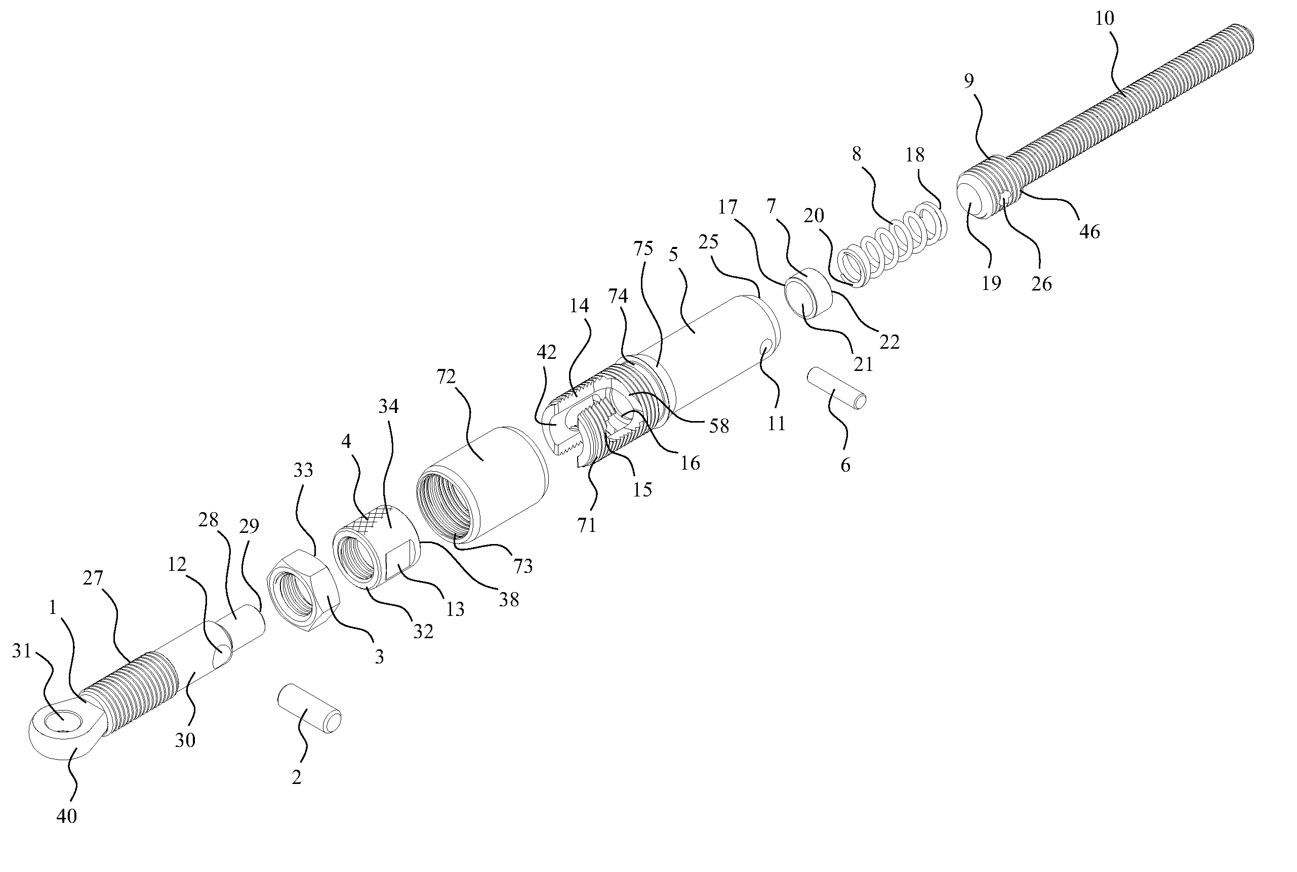
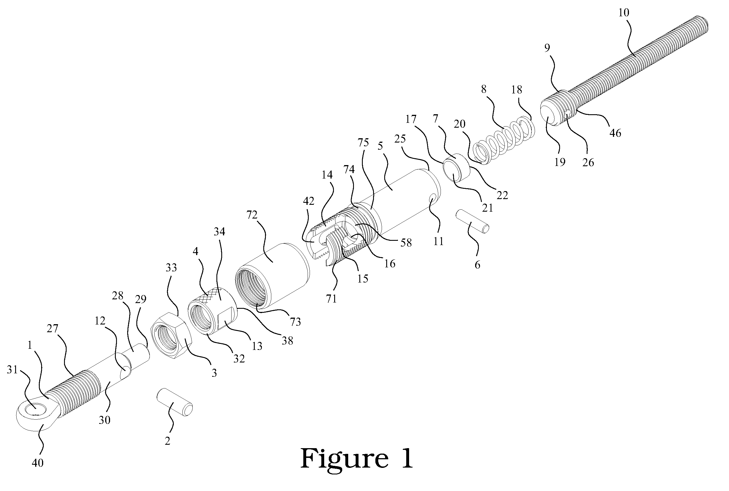
[0036]FIG. 1 displays an exploded view of the present invention. Main insertion pin 1 is fabricated with a threaded section 27, a section 30 which has a diameter stepped down in size preferably below the minor diameter of the threads of the threaded section 27, and an additional section 28 which has been further stepped down in diameter below that of section 30. Clevis shaped head 40 is created by cold working or machining. Hole 31 is drilled through clevis shaped head 40 and an additional hole 12 is drilled through stepped section 30. Jam nut 3 then screws onto threaded shank 27 and knurled hand nut 4 screws onto shank 27 behind jam nut 3. It should be noted that the use of jam nut 3 is optional and its use is only to provide additional security to prevent knurled hand nut 4 from loosening. It should also be noted that clevis shaped head 40 could also consist of a fork or other suitable configuration. Cross pin 2 is then inserted into hole 12 by a press fit or other means which kee...


PUM


Abstract

A locking quick connect fitting allows for the easy attachment and detachment of stays and rigging on sailboats and other related applications. The invention eliminates the need to handle clevis pins and cotter pins when setting up or tearing down the rigging of a sailboat, and especially for the standing rigging of a trailer able sailboat. A more secure lockable device is provided that is less susceptible of being dislodged by the rubbing action of passing lines and sheets. Further, it can be tightened by wrench for even more security. In addition, the fitting helps keep the connection secure even if in the unlocked state and resists the snagging of passing lines. The presented invention is also designed to be modular and readily connectable to the rigging or fittings on existing sailboats.

Description

[0001]This application claims benefit of U.S. Provisional Application Ser. No. 61 / 903,654, filed Nov. 13, 2013, pursuant to 35 USC §119(e).FIELD OF THE INVENTION[0002]The invention relates to rigging-type fittings, in particular, a lockable quick connection fitting for attaching and detaching lines or cables such as the standing rigging used on sailboats.BACKGROUND OF THE INVENTION[0003]In the field of sailing, and especially in the field of trailerable sailboating, it is necessary to raise the mast and attach the corresponding standing rigging to the deck when preparing to launch the boat. The rigging must then be removed and the mast taken down again when the boat is to be put back on the trailer at the end of the day. The current state of the art procedure for the attachment or detachment of the standing rigging is for a person to pull the rigging cables taut by hand, hold the mast in place, and then insert or remove a clevis pin through an eye fitting on both the end of the rigg...

Claims


Application Information

Patent Timeline
Patent Type & Authority Applications(United States)
IPC IPC(8): B63H9/08F16G11/10B63H9/10
CPCB63H9/08F16G11/10B63H9/10B63B15/02F16G11/02F16G11/025F16G11/12Y10T403/295
Inventor TYLASKA, TIMOTHY T.DIXON, THOMAS W.
Owner TYLASKA TIMOTHY T
Why Eureka
Try Eureka