
Electric Vehicle Battery Pack Protection System

a battery pack protection and electric vehicle technology, applied in the field of electric vehicles, can solve problems such as battery pack fire, battery pack catching fire, battery pack fire risk,

Active Publication Date: 2015-05-21
ATIEVA USA INC
View PDF7 Cites 43 Cited by
  • Summary
  • Abstract
  • Description
  • Claims
  • Application Information

AI Technical Summary

Benefits of technology

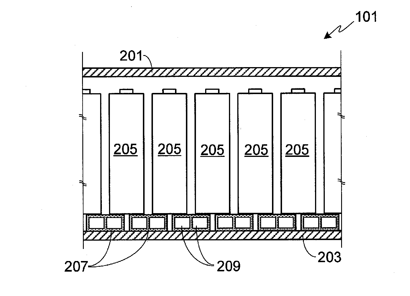
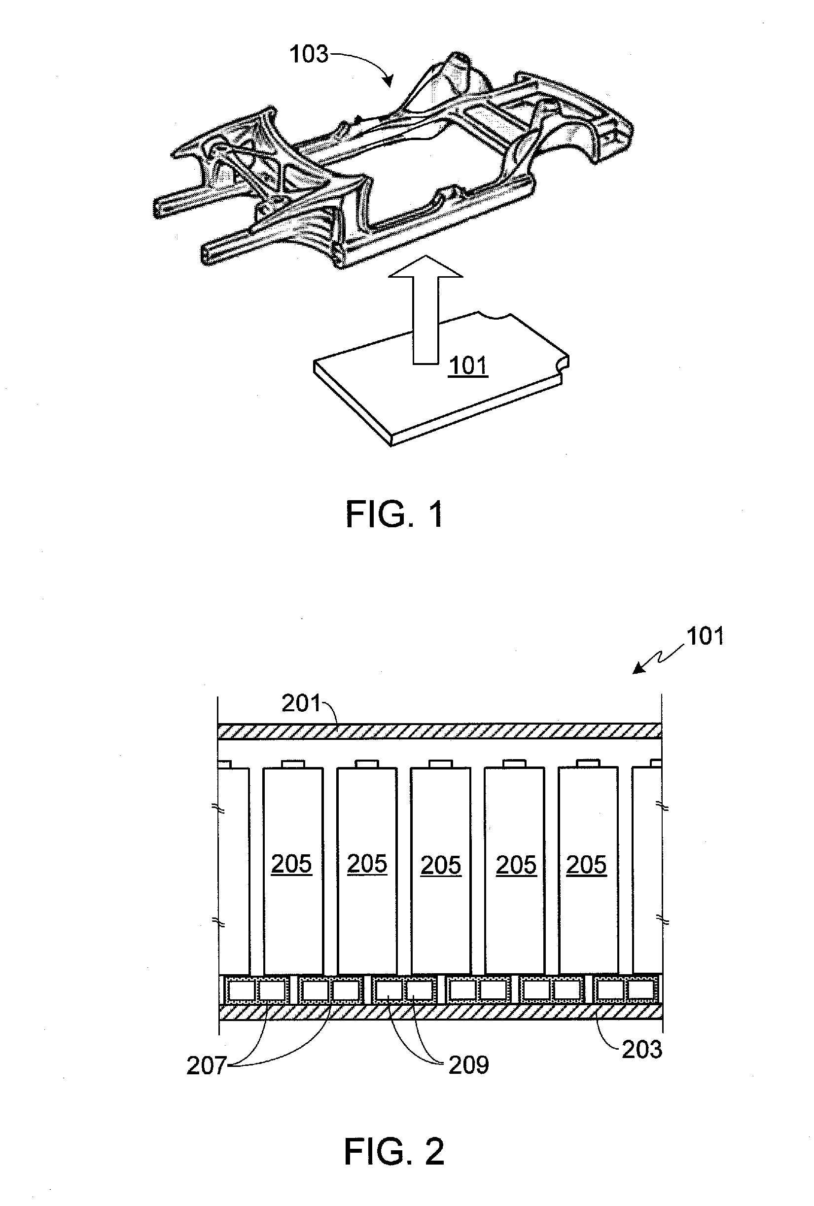
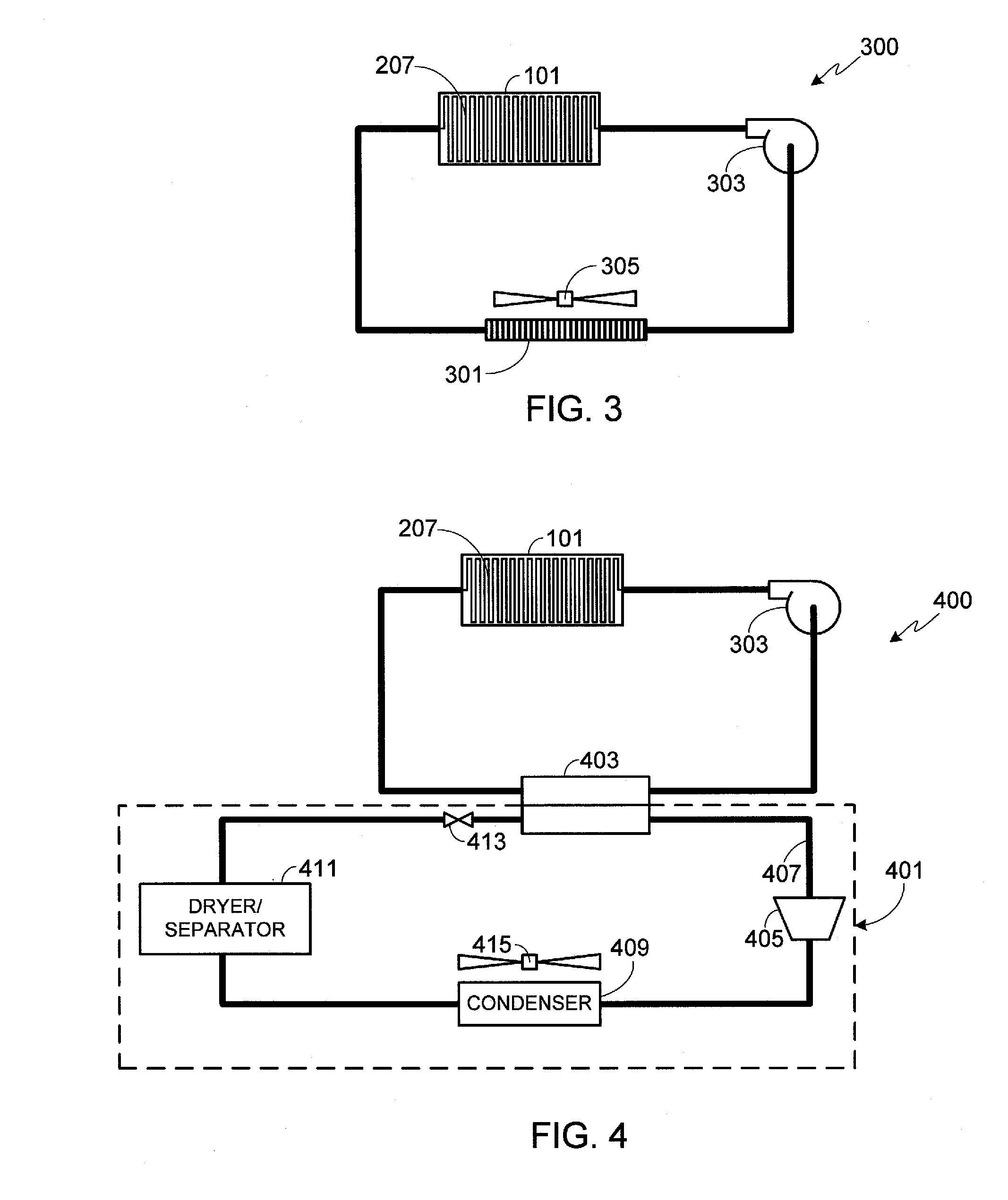
The present invention provides a battery pack protection system for electric vehicles. The system uses a plurality of deformable cooling conduits made of plastic or metal that are placed between the batteries and the battery pack enclosure panel. The cooling conduits can absorb impact energy and protect the battery pack from damage. In addition, a thermally insulating layer can be placed between the cooling conduits and the battery pack enclosure panel. A ballistic shield can also be added to provide additional protection to the battery pack.

Problems solved by technology

In recent years there have been several incidents of a battery pack, either contained within a laptop computer or utilized in a vehicle, catching on fire.
As a result, one of the primary issues impacting consumer confidence with respect to both hybrid and all-electric vehicles is the risk of a battery pack fire.
Rechargeable batteries, due to their chemistries, tend to be relatively unstable and more prone to thermal runaway than non-rechargeable batteries.
Thermal runaway occurs when the battery's internal reaction rate increases to such an extent that it is generating more heat than can be withdrawn.
If reaction rate and heat generation go unabated, eventually the heat generated becomes great enough to cause the battery and materials in proximity to the battery to combust.
Typically thermal runaway is the result of a battery short, damage due to improper use or physical abuse, a manufacturing defect, or exposing the cell to extreme temperatures.

Method used


Image

  • Electric Vehicle Battery Pack Protection System
  • Electric Vehicle Battery Pack Protection System
  • Electric Vehicle Battery Pack Protection System

Examples


Embodiment Construction

[0027]In the following text, the terms “battery”, “cell”, and “battery cell” may be used interchangeably and may refer to any of a variety of different battery configurations and chemistries. Typical battery chemistries include, but are not limited to, lithium ion, lithium ion polymer, nickel metal hydride, nickel cadmium, nickel hydrogen, nickel zinc, and silver zinc. The terms “battery pack” and “battery pack enclosure” may be used interchangeably and refer to an enclosure containing one or more batteries electrically interconnected to achieve the desired voltage and capacity. The term “electric vehicle” as used herein may refer to an all-electric vehicle, also referred to as an EV, a plug-in hybrid vehicle, also referred to as a PHEV, or a hybrid vehicle, also referred to as a HEV, where a hybrid vehicle utilizes multiple sources of propulsion including an electric drive system.

[0028]FIG. 1 provides a perspective view of a battery pack 101 configured to be mounted under vehicle c...


PUM


Abstract

A battery pack protection system is provided for use with an electric vehicle in which the battery pack is mounted under the car. The system utilizes a plurality of deformable cooling conduits located between the lower surface of each of the batteries and the lower battery pack enclosure panel, with a thermal insulator interposed between the conduits and the lower enclosure panel. A layer of thermally conductive material may be included which is interposed between the cooling conduits and the thermal insulator and in contact with a lower surface of each of the cooling conduits. The cooling conduits are configured to deform and absorb impact energy when an object, such as road debris, strikes the lower surface of the lower battery pack enclosure panel. Further protection may be achieved by positioning a ballistic shield, alone or with a layer of compressible material, under the bottom surface of the battery pack.

Description

CROSS-REFERENCE TO RELATED APPLICATION[0001]This application is a continuation-in-part of U.S. patent application Ser. No. 14 / 083,476, filed 19 Nov. 2013, the disclosure of which is incorporated herein by reference for any and all purposes.FIELD OF THE INVENTION[0002]The present invention relates generally to electric vehicles and, more particularly, to a system for providing undercarriage protection to the battery pack of an electric vehicle.BACKGROUND OF THE INVENTION[0003]In response to the demands of consumers who are driven both by ever-escalating fuel prices and the dire consequences of global warming, the automobile industry is slowly starting to embrace the need for ultra-low emission, high efficiency cars. While some within the industry are attempting to achieve these goals by engineering more efficient internal combustion engines, others are incorporating hybrid or all-electric drive trains into their vehicle line-ups. To meet consumer expectations, however, the automobile...

Claims


Application Information

Patent Timeline
IPC IPC(8): H01M10/625F41H5/013F41H5/04F41H7/04B60L50/64
CPCH01M10/5016F41H7/042B60K1/04F41H5/04B60R16/04F41H5/013B60K2001/005H01M2220/20H01M10/6556H01M10/613B60Y2306/01H01M10/625Y02E60/10H01M50/249B60L50/64H01M50/213
Inventor RAWLINSON, PETER DORE
Owner ATIEVA USA INC
Learn More