Solar panel ballasted ground support systems

a solar panel and ground support technology, applied in the direction of heat collector mounting/support, pv power plants, lighting and heating equipment, etc., can solve the problems of panels moving out of optimal position for sunlight capture, difficult protection, and limited structure siz

Inactive Publication Date: 2015-05-21
GAMECHANGE SOLAR LLC
View PDF7 Cites 13 Cited by
  • Summary
  • Abstract
  • Description
  • Claims
  • Application Information

AI Technical Summary

Benefits of technology

[0012]It is accordingly an object of the present invention to provide a ballasting structure, system and method, which obviates the necessity for uneconomical and unwieldy transport of precast very heavy ballasting materials while providing a viable environmentally-resistant position anchoring of solar panel array supporting structures.

Problems solved by technology

These structures are limited in size as a function of rooftop areas and roof support capabilities
A second major type of support system is referred to as a “ground system”, which, as opposed to roof systems, can be and often is quite extensive in area (solar panels provide energy as a function of areal sunlight capture and require large areas for viable energy production) and which are accordingly difficult to protect and are highly susceptible to weather conditions.
In particular, high or sustained wind conditions may either damage solar panels over time or, more commonly, cause the panels to move out of optimal position for sunlight capture.
Because of the extensive area occupied by viable energy producing solar panels and the large number of panels typically used, efficiencies of scale and proper deployment present numerous problems.
Full off-site structure assembly is however nearly impossible because of the weight of concrete encased components and the extremely unwieldy large structure for transport and proper positioning.
The current method of off-site ballasting and transport though effective in providing a final ballasted structure has however proven to still be unwieldy and uneconomical, especially with the extent of ballasting required for large-scale arrays.
In addition proper alignment of pre-cast components on uneven ground has proven to be problematic.

Method used


Image

  • Solar panel ballasted ground support systems
  • Solar panel ballasted ground support systems
  • Solar panel ballasted ground support systems

Examples


Embodiment Construction

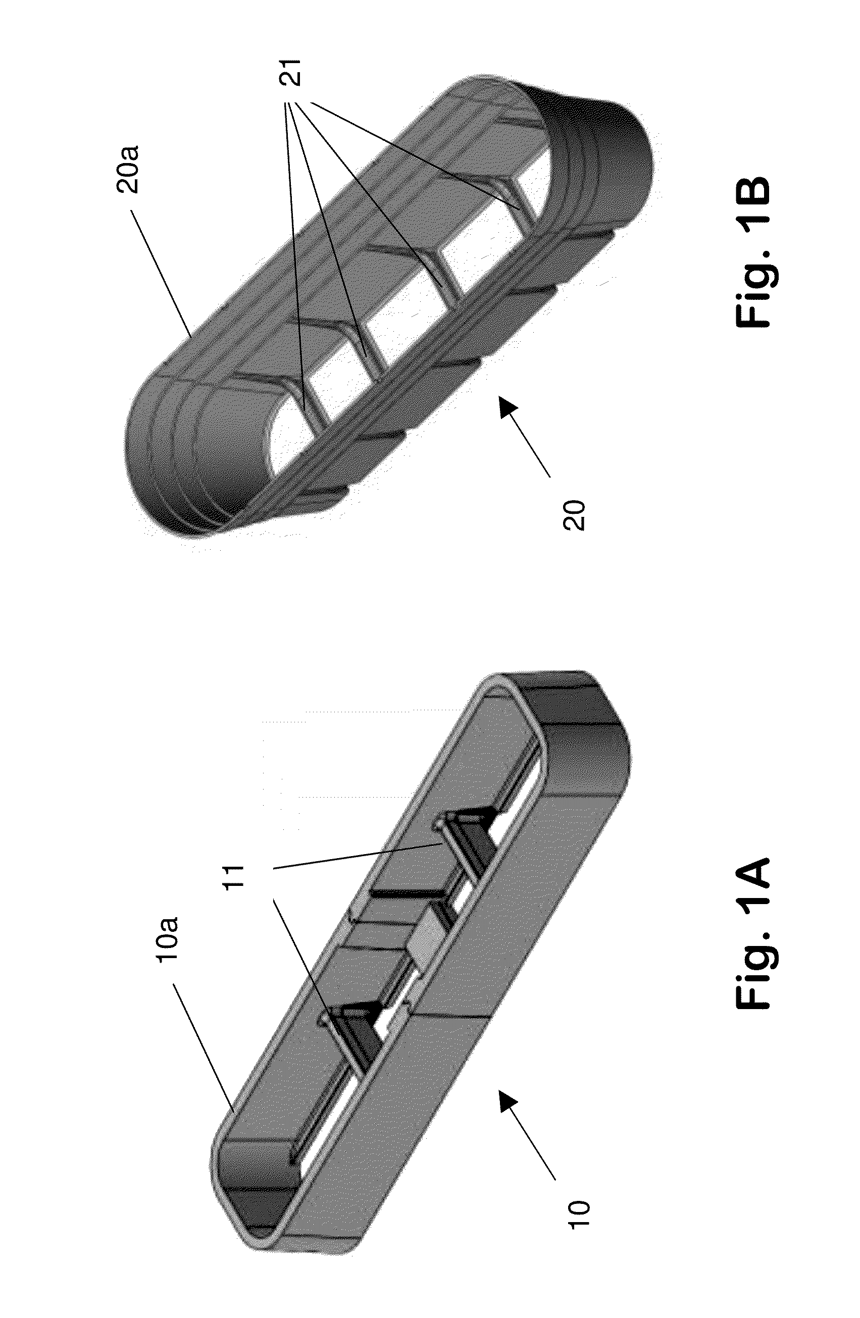
[0042]With reference to the drawings, FIGS. 1A and 1B depict two examples 10 and 20 of disposable one time use framing tubs utilizable in the method and system of the present invention. The disposable framing tub 10 is comprised of a structurally supportive Styrofoam material and the framing tub 20 is a plastic material such as polystyrene, polyethylene and the like which may further require temporary shoring of the side while concrete is poured therein. The tubs are configured with continuous side walls 10a and 20a respectively but with open tops and bottoms. Plastic cross rails, bars, or beams 11 and 21 respectively extend interiorally from opposing side walls 10a and 20a and function to provide resistance against the outward spreading of the plastic under poured concrete pressure.

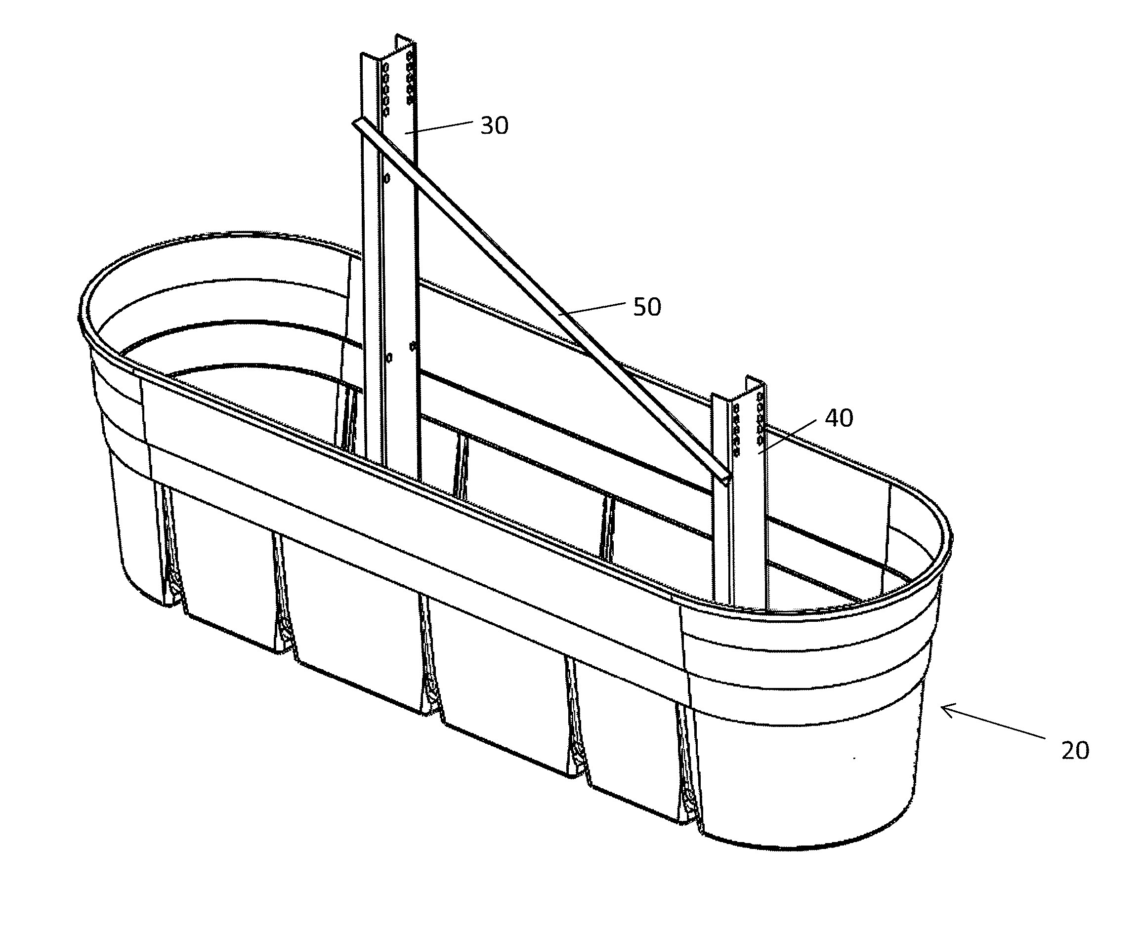
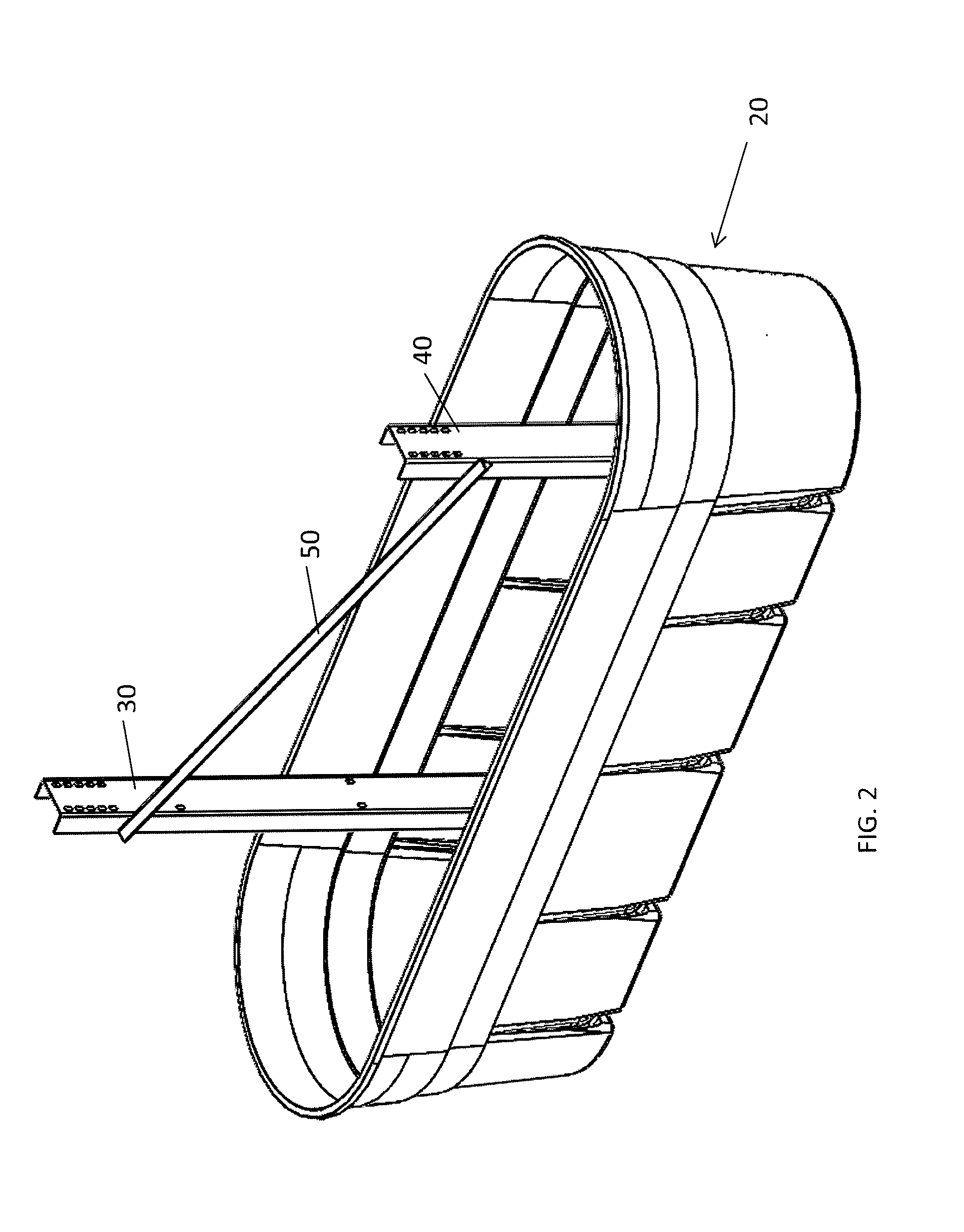
[0043]Vertically aligned North Post 30 and South Post 40 are shown in FIG. 2 within framing tub 20, with the posts being angularly attached with bar 50 for subsequent solar panel support. The framing tub...


PUM

PropertyMeasurementUnit
lengthaaaaaaaaaa
lengthaaaaaaaaaa
distanceaaaaaaaaaa

Abstract

A structure, system and method for the in situ ballasting of solar panel ground support structures, the method, system and structures comprising the positioning of supporting posts or anchoring elements therefor within a peripherally enclosing frame, having an open top and preferably open bottom, on the ground at a final solar panel array supporting position. The supporting posts or anchoring elements therefor are vertically aligned and maintained in position relative to each other and a ballast material, such as concrete, is poured into the enclosing frame around the supporting posts or anchoring elements therefor in the final solar panel supporting position thereof with the ballast material being allowed to harden. A solar panel support structure is constructed with the solar panel support structure being ballasted, in final solar panel array position, in situ. Thereafter solar panels are placed on the ballasted support structure to provide the solar panel array.

Description

[0001]This application is a non-provisional application of provisional application Ser. No. 61 / 906,085, filed Nov. 19, 2013, the entire disclosure of which is incorporated herein by reference thereto.FIELD OF THE INVENTION[0002]This invention relates to support systems for solar panels and particularly to ground systems with ballasted support provided in situ.BACKGROUND[0003]Large-scale solar panel arrays are currently provided with two major types of support systems. A first type is referred to as a roof system, which, as the name implies, embodies relatively light structures which are integrated with rooftops and roofing structures. These structures are limited in size as a function of rooftop areas and roof support capabilities[0004]A second major type of support system is referred to as a “ground system”, which, as opposed to roof systems, can be and often is quite extensive in area (solar panels provide energy as a function of areal sunlight capture and require large areas for ...

Claims


Application Information

Patent Timeline
Patent Type & Authority Applications(United States)
IPC IPC(8): H01L31/042H01L31/18
CPCH01L31/18H01L31/0422F24S25/11F24S25/12F24S2025/014F24S2025/02H02S20/10Y02E10/47Y02E10/50Y10T29/49355
Inventor WORDEN, ANDREW BARRON
Owner GAMECHANGE SOLAR LLC
Why Eureka
Try Eureka