

Variable magnetomotive force rotary electric machine and control device for variable magnetmotive force rotary electric machine
- Summary
- Abstract
- Description
- Claims
- Application Information
AI Technical Summary
Benefits of technology
Problems solved by technology
Method used
Image

Examples
Embodiment Construction
[0026]Selected embodiments will now be explained with reference to the drawings. It will be apparent to those skilled in the art from this disclosure that the following descriptions of the embodiments are provided for illustration only and not for the purpose of limiting the invention as defined by the appended claims and their equivalents.
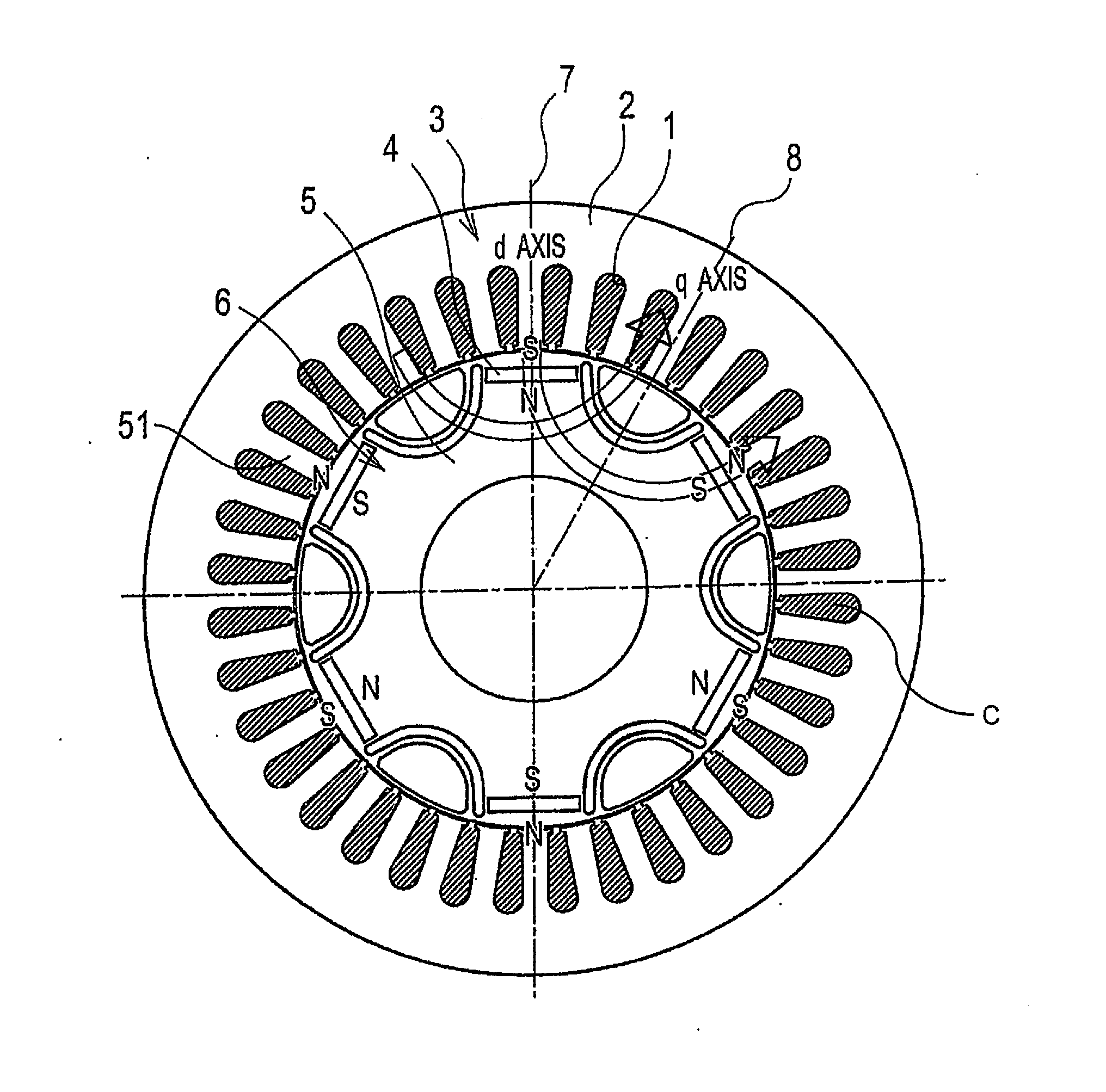
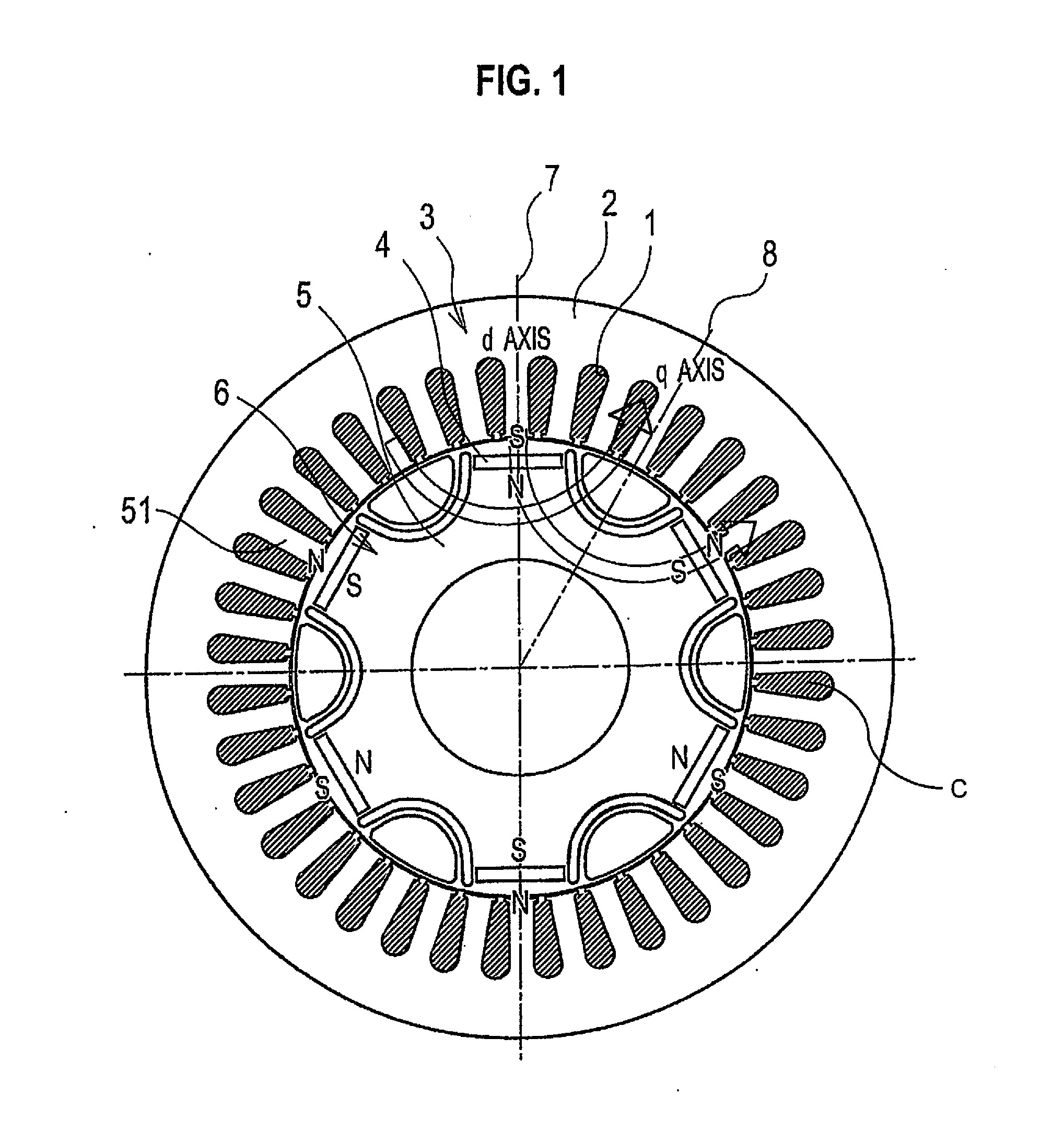
[0027]Referring initially to FIG. 1, a rotary electric machine is illustrated in accordance with one illustrative embodiment. The rotary electric machine has a plurality of slots 1 formed by a stator core 2. The rotary electric machine includes an annular stator 3 and a rotor 6, which is positioned on the inner circumferential side of the stator 3. The rotary electric machine is coaxial with the stator 3, as shown in FIG. 1. An air gap is formed as a clearance between the stator 3 and the rotor 6.
[0028]The stator 3 includes the stator core 2 and a plurality (e.g., 36) of teeth 51 that protrude from the stator core 2 toward the inner circumferentia...
PUM
 Abstract
Description
Claims
Application Information