Heat treatable coated article with low-e coating having zinc stannate based layer between ir reflecting layers and corresponding method

a coating and low-e coating technology, applied in glass tempering apparatuses, instruments, manufacturing tools, etc., can solve the problems of tempered glass being more expensive, and achieve low sheet resistance characteristics, low resistance (rs), and some performance and color change cannot be avoided

Active Publication Date: 2015-05-21
GUARDIAN GLASS LLC +1
View PDF13 Cites 37 Cited by
  • Summary
  • Abstract
  • Description
  • Claims
  • Application Information

AI Technical Summary

Benefits of technology

[0008]Due to the mentioned processes occurring within the coating during the HT process, some performance and color change cannot be avoided. However, it would be desirable for most or much of these changes to occur at the beginning of, or within a short period of, a HT process (e.g., within the first 8-16 minutes, or within the first 10-12 or 10-16 minutes of HT), so that the heat treated product substantially hits the final desired color values within the first 16 minutes or so of the HT process, so that the product can remain substantially stable with respect to color change over an increased tempering time period of the HT process, independent of the furnace type, if that should occur. Of course, sometimes the HT period will be less than 16 minutes. For example, assuming an example HT process of 24 minutes, it would be desirable for the coated article to substantially realize the final desired color values within the first 16 minutes or so

Problems solved by technology

As tempered glass is more expensive compared to non-tempered glass, tempered coated articles are typically only utilized if required.
D

Method used


Image

  • Heat treatable coated article with low-e coating having zinc stannate based layer between ir reflecting layers and corresponding method
  • Heat treatable coated article with low-e coating having zinc stannate based layer between ir reflecting layers and corresponding method
  • Heat treatable coated article with low-e coating having zinc stannate based layer between ir reflecting layers and corresponding method

Examples


examples

FIG. 1 Embodiment

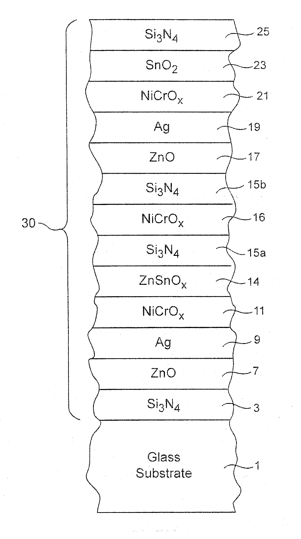
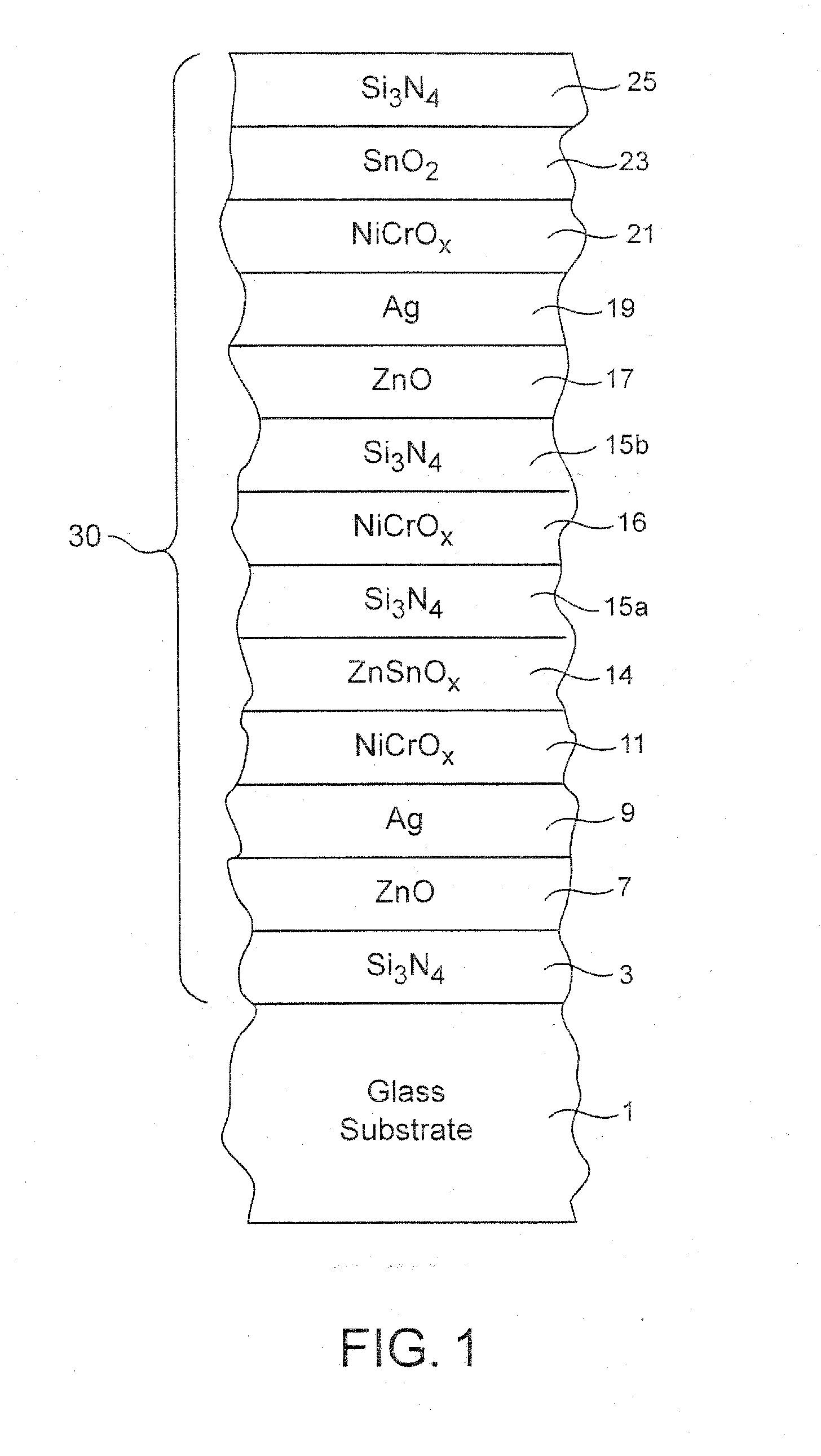
[0049]The following examples were made via sputtering a coating as shown in FIG. 1 on a 6 mm thick clear glass substrate 1 so as to have the layer stacks set forth below. The thicknesses are in units of angstroms (Å). It can be seen that the Comparative Example was the same as Example 1 of this invention except that the zinc stannate layer 14 in Example 1 of this invention was used instead of the tin oxide layer in the Comparative Example (“n / a” means that the applicable layer was not present in that example). In other words, Example 1 according to this invention was the same as the Comparative Example (CE) except that the tin oxide layer in the middle dielectric portion of the CE was replaced with the zinc stannate layer 14 in Example 1 according to this invention.

LayerComparativeExampleGlass SubstrateExample1Si3N4354354ZnAlO100100Ag110110NiCrOx3030SnO2472n / aZnSnOn / a472Si3N4120120NiCrOx4040Si3N4204204ZnO100100Ag207207NiCrOx3030SnO2100100Si3N4120120

[0050]After being...

examples

FIG. 2 Embodiment

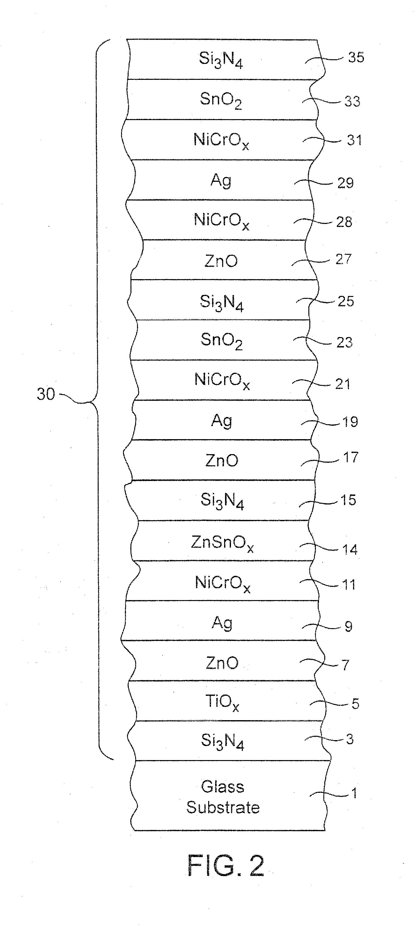
[0054]The following examples were made via sputtering a coating as shown in FIG. 2 on a 6 mm thick clear glass substrate 1 so as to have the layer stacks set forth below. The thicknesses are in units of angstroms (Å). It can be seen that the Comparative Example (CE) was the same as Example 2 of this invention except that the tin oxide layer adjacent the zinc stannate layer 14 in the CE was not present in Example 2 of this invention (“n / a” means that the applicable layer was not present in that example). In other words, Example 2 according to this invention was essentially the same as the Comparative Example (CE) except for the zinc stannate thickness and that the zinc stannate layer 14 in Example 2 was in direct contact with the NiCrOx contact layer 11 (as opposed to having a tin oxide layer therebetween in the CE). The zinc stannate layers were sputtered via ZnSn targets with a Zn / Sn wt. % ratio of 52 / 48.

LayerComparativeExampleGlass SubstrateExample2Si3N4136136TiOx...


PUM

PropertyMeasurementUnit
Fractionaaaaaaaaaa
Fractionaaaaaaaaaa
Fractionaaaaaaaaaa

Abstract

A coated article is provided which may be heat treated (e.g., thermally tempered) in certain example instances. In certain example embodiments, the coated article includes a low-emissivity (low-E) coating having a zinc stannate based layer provided over a silver-based infrared (IR) reflecting layer, where the zinc stannate based layer is preferably located between first and second silver based IR reflecting layers. The zinc stannate based layer may be provided between and contacting (i) an upper contact layer of or including Ni and/or Cr (or Ti, or TiOx), and (ii) a layer of or including silicon nitride.

Description

[0001]This invention relates to a coated article including a low emissivity (low-E) coating. In certain example embodiments, the coated article may be heat treated (e.g., thermally tempered, heat bent and / or heat strengthened). In certain example embodiments of this invention, the coated article includes a zinc stannate based layer provided proximate (e.g., over) a silver-based infrared (IR) reflecting layer, where the zinc stannate based layer is preferably located between first and second silver based IR reflecting layers. In certain example embodiments, the zinc stannate based layer is provided between and contacting (i) an upper contact layer of or including Ni and / or Cr, and (ii) a layer of or including silicon nitride, so that for example the layer stack moving away from the glass substrate may include layers comprising the following materials: glass . . . Ag / NiCrOx / ZnSnO / SiN . . . A . . . Low-E coatings according to various embodiments of this invention may, for example, have...

Claims


Application Information

Patent Timeline
IPC IPC(8): C03C17/36C03B27/00C03C17/34
CPCC03C17/366C03C17/3435C03B27/00C03C17/3639C03C17/3644C03C17/3613C03C17/36C03C17/3626C03C17/3652Y10T428/12549Y10T428/2495Y10T428/265
Inventor PALLOTTA, PIERREFERREIRA, JOSELAGE, HERBERTFRANK, MARCUS
Owner GUARDIAN GLASS LLC
Why Eureka
Try Eureka