Nonaqueous secondary battery

a secondary battery, non-aqueous technology, applied in the direction of batteries, cell components, cell component details, etc., can solve the problems of battery function impairment, safety hazards, self-discharge, etc., and achieve the effect of resisting change in shape, ionic conductivity and mechanical strength

Active Publication Date: 2015-05-21
SEMICON ENERGY LAB CO LTD
View PDF3 Cites 22 Cited by
  • Summary
  • Abstract
  • Description
  • Claims
  • Application Information

AI Technical Summary

Benefits of technology

[0013]The separator is generally formed using a porous material. The size and the shape of a pore formed in the separator and the proportion of the volume of pores in the layer of the separator (i.e., porosity) depend on a material of the separator. As the size of the pore in the separator is larger or the proportion of the volume of the pores (porosity) is higher, ionic conductivity becomes higher whereas a function of insulating the electrodes is more impaired. In the case where a whisker-like structure (whisker) is generated, the whisker-like structure penetrates through the separator more easily, which lowers insulation performance. On the other hand, the pore in the separator is less likely to be blocked by a separated lump of the above-described irreversible component formed through the deposition of lithium or other components or by a particle of an active material separated from an active material layer; accordingly, ionic conductivity is kept more easily.
[0039]One embodiment of the present invention can provide a secondary battery that can be changed in shape, i.e., a secondary battery having flexibility. One embodiment of the present invention can provide a novel separator which can resist change in shape in a secondary battery having flexibility.

Problems solved by technology

If the electrodes directly contact each other in the lithium-ion secondary battery, an uncontrollable high current flows between the electrodes, and, for example, a large amount of heat is generated, causing a safety hazard in some cases.
Even when a safety hazard is not caused, self-discharge occurs and a function as the battery is impaired.
Furthermore, in a process of manufacturing or charging / discharging the lithium-ion secondary battery, a part of carrier ions contributing to charging / discharging is deposited on a surface of the negative electrode and becomes an irreversible component, which impairs a function as the battery.
The structure might pass through a pore in the separator and connect the electrodes depending on the property of the separator, which also causes a problem.
In the case where a whisker-like structure (whisker) is generated, the whisker-like structure penetrates through the separator more easily, which lowers insulation performance.

Method used


Image

  • Nonaqueous secondary battery
  • Nonaqueous secondary battery
  • Nonaqueous secondary battery

Examples


embodiment 1

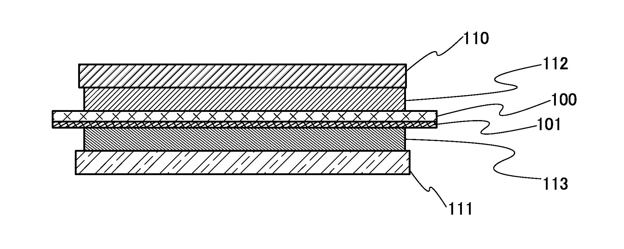
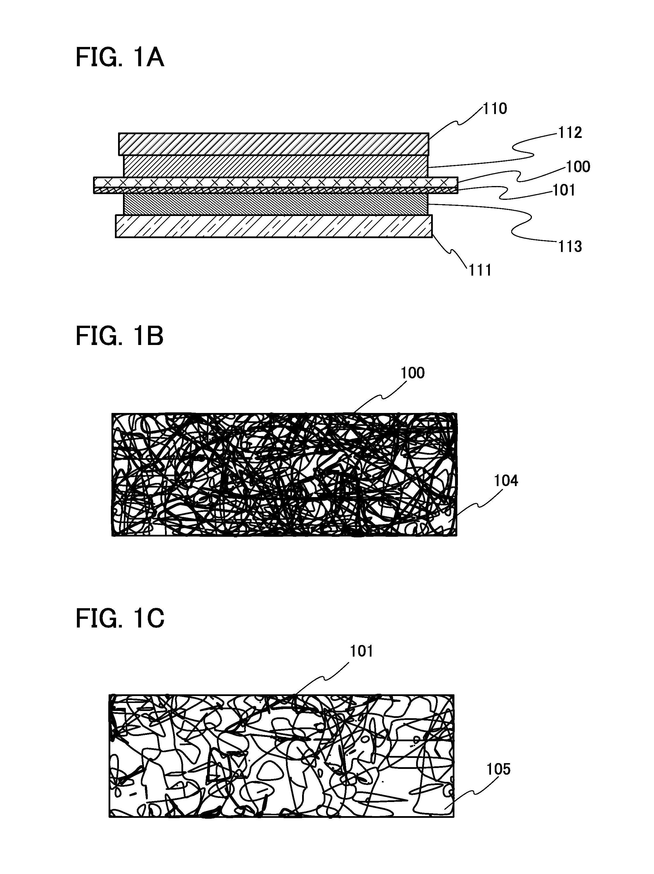
[0065]Description is given below of a method for manufacturing a lithium-ion secondary battery of one embodiment of the present invention with reference to FIG. 1A. First, a cross-sectional schematic view of a stack of a positive electrode current collector 110, a positive electrode active material layer 112, a first separator 100, a second separator 101, a negative electrode active material layer 113, and a negative electrode current collector 111 is shown. Details of the current collector and the active material layer are described later. Note that the active material layer can be formed on both surfaces of the current collector, and the secondary battery can have a stacked-layer structure.

[0066]FIGS. 1B and 1C are enlarged cross-sectional schematic views of the first separator 100 and the second separator 101, respectively. The first separator 100 and the second separator 101 have a first pore 104 and a second pore 105, respectively. The size of the first pore 104 is different fr...

embodiment 2

[0125]In this embodiment, a method for manufacturing a lithium-ion secondary battery of one embodiment of the present invention is described below with reference to FIG. 4A. First, a cross-sectional schematic view of a stack of the positive electrode current collector 110, the positive electrode active material layer 112, the second separator 101, the first separator 100, a third separator 102, the negative electrode active material layer 113, and the negative electrode current collector 111 is shown. Note that the active material layer can be formed on both surfaces of the current collector, and the secondary battery can have a stacked-layer structure.

[0126]FIGS. 4B, 4C, and 4D are enlarged cross-sectional schematic views of the second separator 101, the first separator 100, and the third separator 102, respectively. The first separator 100, the second separator 101, and the third separator 102 have the first pore 104, the second pore 105, and a third pore 106, respectively. Note t...

embodiment 3

[0132]In this embodiment, structures of a secondary battery including the separator described in Embodiment 1 or Embodiment 2 are described with reference to FIGS. 5A to 5C, FIG. 6, and FIGS. 7A and 7B.

(Coin-Type Secondary Battery)

[0133]FIG. 5A is an external view of a coin-type (single-layer flat type) secondary battery. FIG. 5B is a cross-sectional view of the coin-type secondary battery.

[0134]In a coin-type secondary battery 300, a positive electrode can 301 doubling as a positive electrode terminal and a negative electrode can 302 doubling as a negative electrode terminal are insulated from each other and sealed by a gasket 303 made of, for example, polypropylene. A positive electrode 304 includes a positive electrode current collector 305 and a positive electrode active material layer 306 provided in contact with the positive electrode current collector 305. A negative electrode 307 includes a negative electrode current collector 308 and a negative electrode active material lay...


PUM

PropertyMeasurementUnit
curvature radiusaaaaaaaaaa
particle diameteraaaaaaaaaa
thicknessaaaaaaaaaa

Abstract

To provide a novel structure of a separator in a secondary battery. A nonaquesous secondary battery includes a positive electrode, a negative electrode, an electrolyte solution, a first separator, and a second separator. The first separator and the second separator are provided between the positive electrode and the negative electrode. The first separator is provided with a first pore, the second separator is provided with a second pore, and the size of the first pore is different from the size of the second pore. Furthermore, the proportion of the volume of the first pores in the first separator is different from the proportion of the volume of the second pores in the second separator.

Description

BACKGROUND OF THE INVENTION[0001]1. Field of the Invention[0002]One embodiment of the present invention relates to a nonaqueous secondary battery and a method for manufacturing the nonaqueous secondary battery.[0003]Note that one embodiment of the present invention is not limited to the above technical field. The technical field of one embodiment of the invention disclosed in this specification and the like relates to an object, a method, or a manufacturing method. In addition, one embodiment of the present invention relates to a process, a machine, manufacture, or a composition of matter. Specifically, examples of the technical field of one embodiment of the present invention disclosed in this specification include a semiconductor device, a display device, a light-emitting device, a power storage device, a storage device, a method for driving any of them, and a method for manufacturing any of them.[0004]2. Description of the Related Art[0005]In recent years, a variety of power stor...

Claims


Application Information

Patent Timeline
Patent Type & Authority Applications(United States)
IPC IPC(8): H01M2/16H01M10/0525H01M10/04H01M50/119H01M50/126H01M50/449H01M50/457
CPCH01M2/1686H01M10/04H01M2220/20H01M2220/30H01M10/0525H01M50/449H01M50/457H01M50/119H01M50/126Y02E60/10Y02T10/70
Inventor YAMAZAKI, SHUNPEI
Owner SEMICON ENERGY LAB CO LTD
Why Eureka
Try Eureka