

Valve seats for use in fracturing pumps
a technology of reciprocating pumps and valve seats, which is applied in the direction of machines/engines, liquid fuel engines, and positive displacement liquid engines, etc., can solve the problems of corrosion, erosion and/or pitting of the surface of the valve assembly, and the replacement of the valve seat is more difficult and cumbersome than the replacement of the valve body
- Summary
- Abstract
- Description
- Claims
- Application Information
AI Technical Summary
Benefits of technology
Problems solved by technology
Method used
Image

Examples
Embodiment Construction
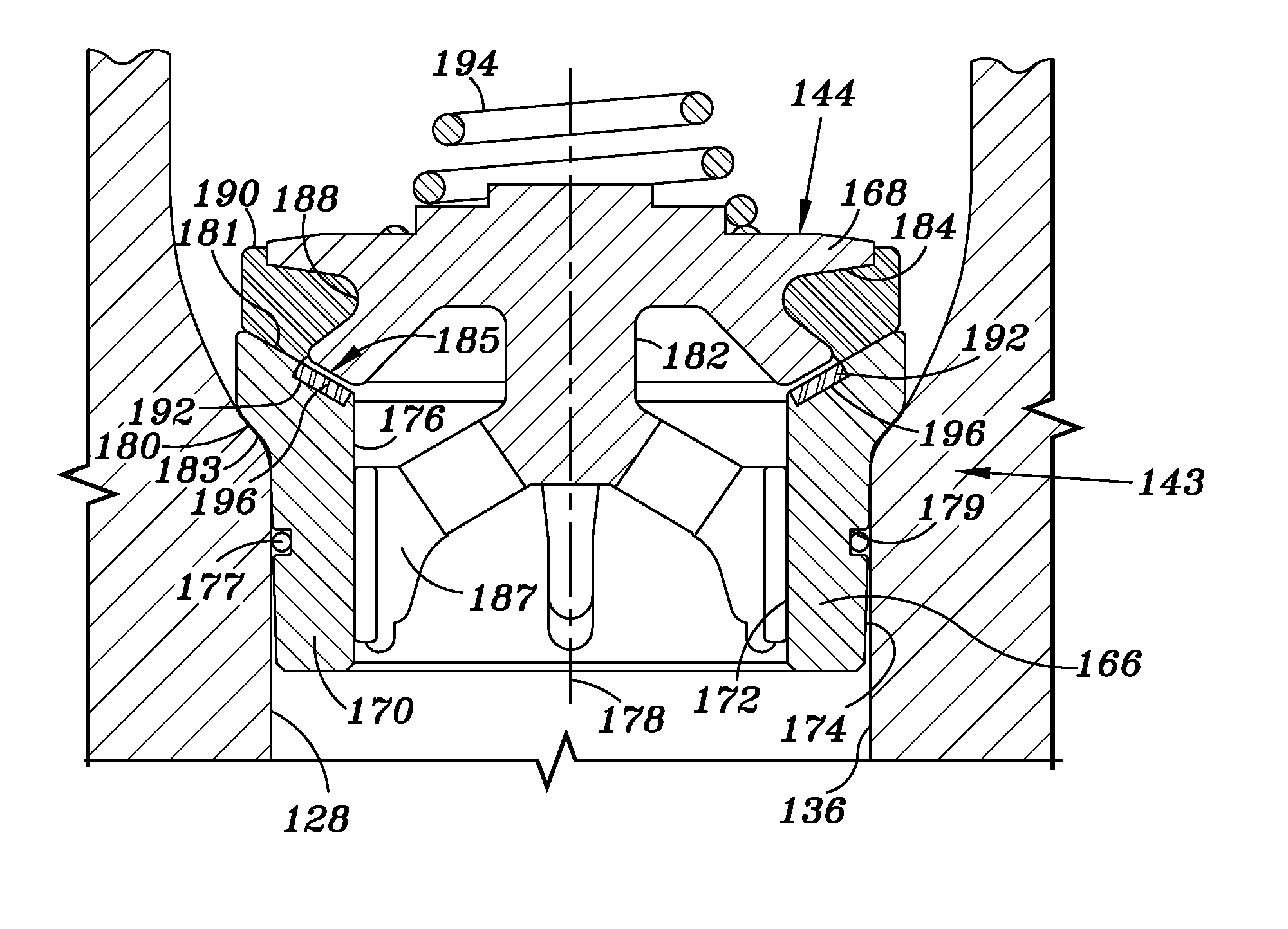
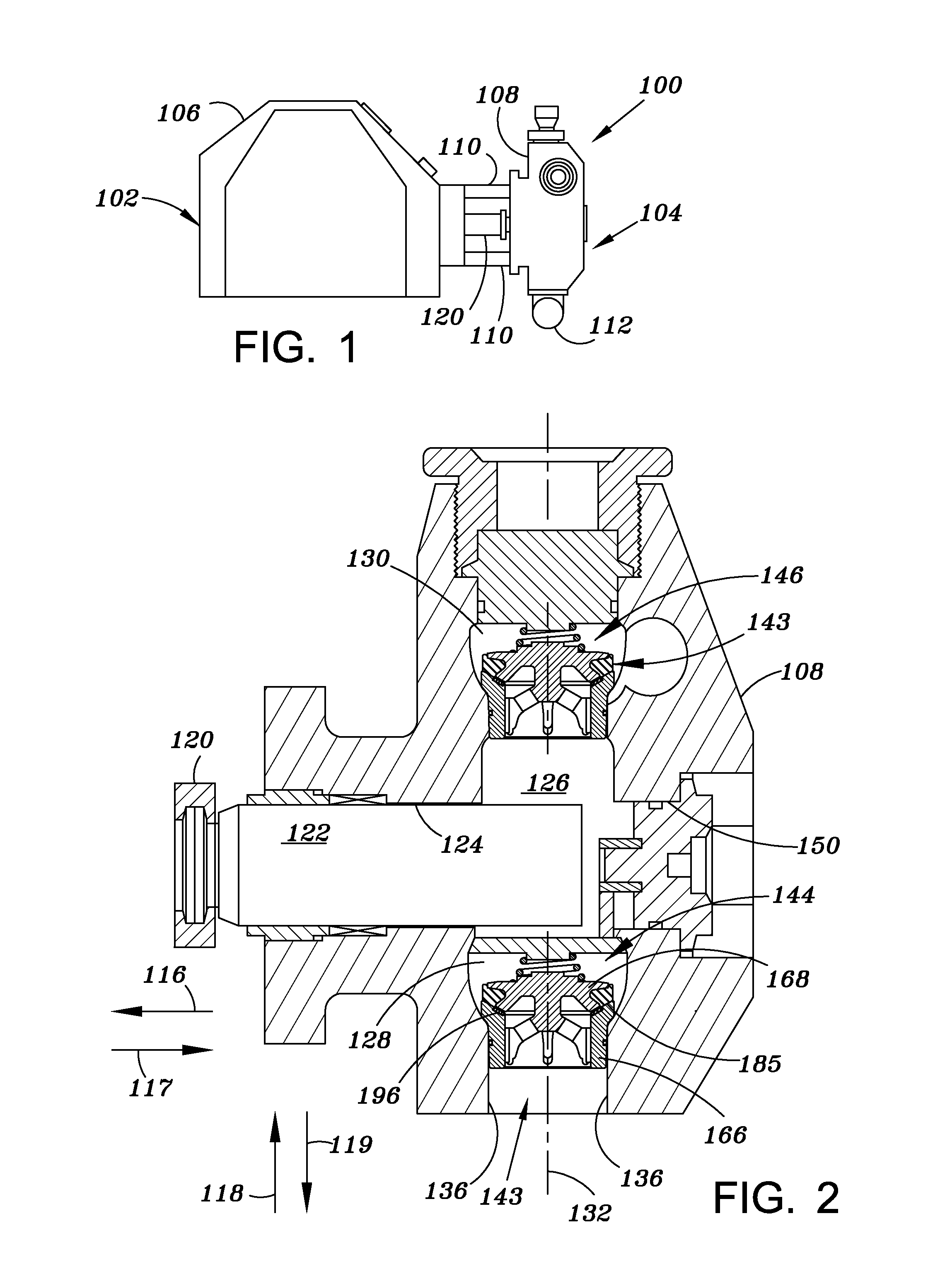
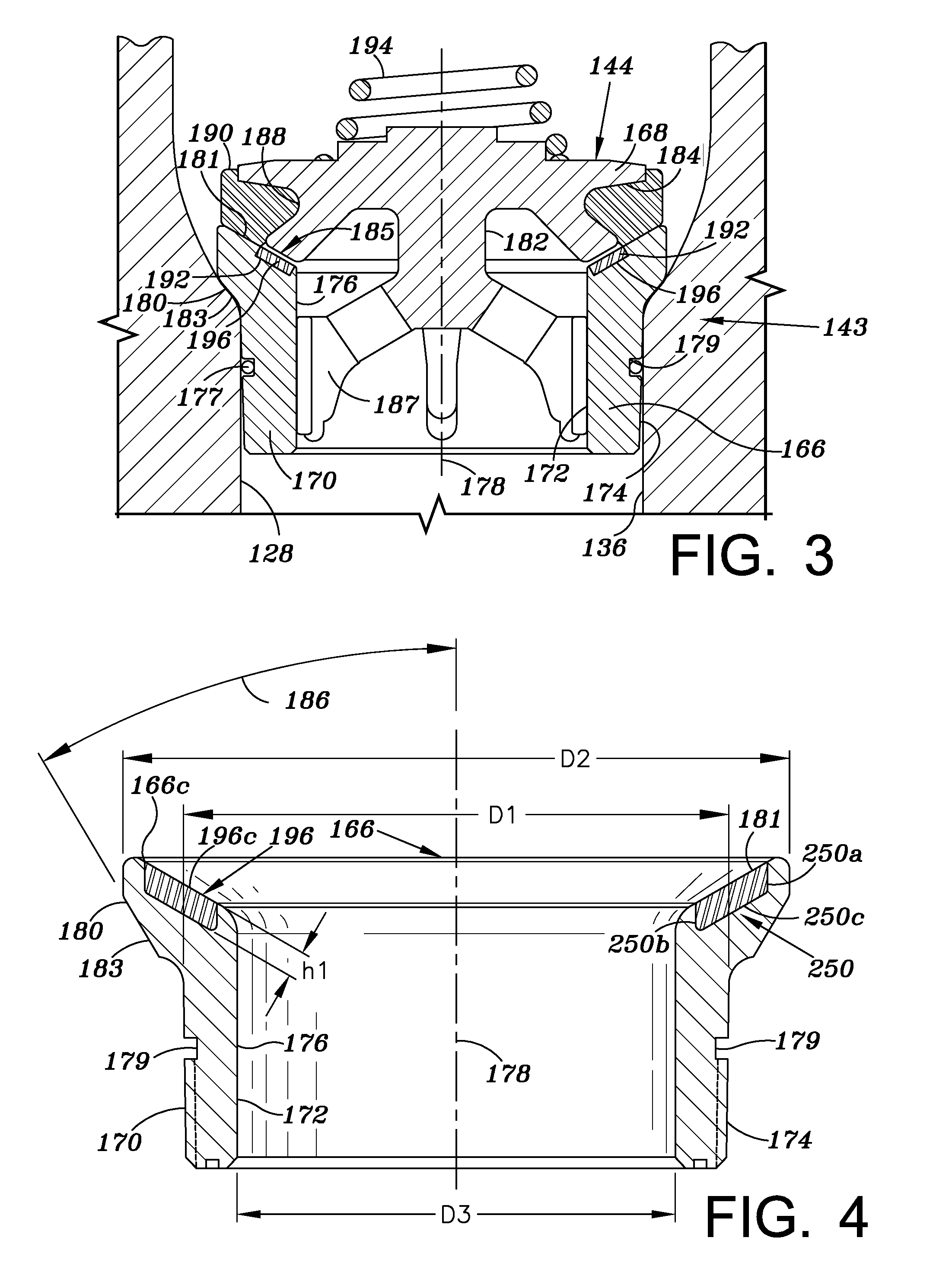
[0060]Referring to FIGS. 1-3, an illustrative embodiment of a reciprocating pump assembly 100 is presented in which an insert 196 (FIG. 3) is employed to reduce damage to, and thus, extend the operating life of, a valve assembly 143, due to corrosion, erosion, pitting or the like. In the embodiment illustrated in FIGS. 1-3, the insert 196 is formed of a high strength ceramic material; however, it should be understood that insert 196 may be otherwise formed. In FIGS. 1-3, the reciprocating pump assembly 100 includes a power end portion 102 and a fluid end portion 104 operably coupled thereto. The power end portion 102 includes a housing 106 in which a crankshaft (not shown) is disposed, the crankshaft is driven by an engine or motor (not shown). The fluid end portion 104 includes a fluid end block or fluid cylinder 108, which is connected to the housing 106 via a plurality of stay rods 110. In operation and as discussed in further detail below, the crankshaft reciprocates a plunger r...
PUM
| Property | Measurement | Unit |
|---|---|---|
| angle | aaaaa | aaaaa |
| pressures | aaaaa | aaaaa |
| pressures | aaaaa | aaaaa |
Abstract
Description
Claims
Application Information