Prism for projection optical system and optical system having same

Active Publication Date: 2015-06-11
KONICA MINOLTA INC
View PDF6 Cites 12 Cited by
  • Summary
  • Abstract
  • Description
  • Claims
  • Application Information

AI Technical Summary

Benefits of technology

[0023]In the prism for a projection optical system, the medium-refractive-index material is preferably Al2O3, the low-refractive-index material is preferably MgF2, and the high-refractive-index material is preferably TiZrO4. According to such a configuration, materials having refractive indices preferable for forming a dielectric multilayer suitable for laser light in the predetermined wavelength ranges radiated by the illumination light source can be easily obtained.
[0024]In the prism for a projection optical system, an angle of incidence of a beam passing through the second surface is preferably 56° when a substrate glass of the prism for a projection optical system has a refractive index of 1.52. According to such a configuration, the reflectivity of the projection light incident via the air gap can be minimized and generation of unnecessary reflected light by the second surface that is a p

Problems solved by technology

If light (projection light, for example) passing through a surface in contact with the air gap of the prism for the projection optical system is partly reflected, light leaks into the prism, which not only degrades light use efficiency but may also damage optical components, adhesives, and the like owing to heat caused by unnecessary reflected light.
In particular, when a laser light source with high power output is used, the degree of heat due to unnecessary reflective light becomes high, which is undesirable.
If light to be transmitted is partly reflected, the reflected quantity is a loss in the light quantity and the light use efficien

Method used


Image

  • Prism for projection optical system and optical system having same
  • Prism for projection optical system and optical system having same
  • Prism for projection optical system and optical system having same

Examples


first embodiment

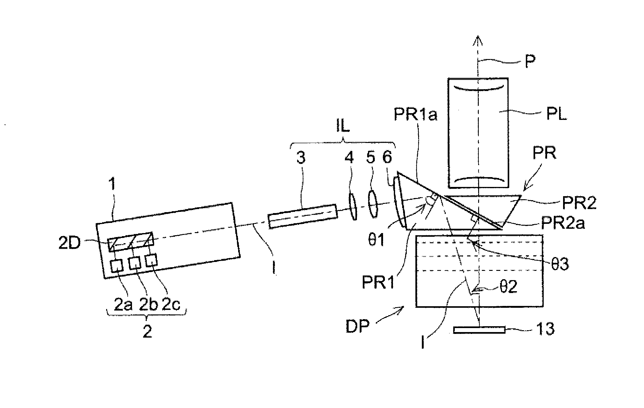
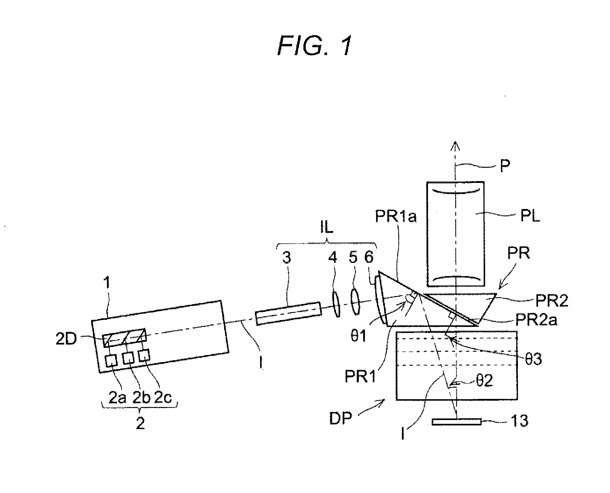
[0044]For example, an optical system according the first embodiment shown in FIG. 1 includes an illumination optical system IL configured to guide illumination light I from an illumination light source 1 configured to radiate laser light, a prism PR for a projection optical system, a dichroic prism DP, an image display device 13, and a projection optical system PL configured to guide projection light P from the image display device 13 to a projection screen.

[0045]The illumination light source 1 includes a laser light source 2 having semiconductor lasers of three primary colors including a blue laser light source 2a configured to emit blue light in a first wavelength range, a green laser light source 2b configured to emit green light in a second wavelength range, and a red laser light source 2c configured to emit red light in a third wavelength range, for example. Laser light rays from the multiple light sources are combined into one illumination light ray I via a light combining uni...

second embodiment

[0068]Next, an optical system using only a prism for a projection optical system will be describe as a second embodiment with reference to FIGS. 4 and 5. The present embodiment is what is called a single-chip optical system configured to display a three-color image by using one image display device 13. Components having the same configurations as those in the first embodiment will be described using the same reference numerals.

[0069]The optical system of the present embodiment also includes an illumination light source 1 having a laser light source 2 including semiconductor lasers of three primary colors, an illumination optical system IL, a prism PR for a projection optical system, an image display device 13, and a projection optical system PL.

[0070]The prism PR for a projection optical system according to the present embodiment also includes a first prism PR1 on which illumination light I is incident and a second prism PR2 from which projection light P exits, and an air gap is pro...

example 1

[0087]Next, Example 1 of the antireflective film 7 according to the present embodiment will be described with reference to FIGS. 7A and 7B. FIG. 7A shows the configuration and the characteristics of the antireflective film 7 according to Example 1, and FIG. 7B shows the reflectivity of the antireflective film 7.

[0088]As shown in FIG. 7A, the antireflective film 7 according to Example 1 has, on a glass substrate, a seven-layer configuration of a laminate of Al2O3 having a refractive index of 1.62 as first and third layers, a mixed film of TiO2 and La2O3 having a refractive index of 2.05 as second, fourth and sixth layers, and MgF2 having a refractive index of 1.38 as fifth and seventh layers.

[0089]Furthermore, the thicknesses d and the ratios of the optical film thicknesses nd to the designed dominant wavelength λ0 of the first to seventh layers are 91 nm and 0.27, 137 am and 0.51, 102 nm and 0.30, 20 nm and 0.07, 23 nm and 0.06, 108 nm and 0.40, and 114 nm and 0.29, respectively.

[00...


PUM


Abstract

A prism for a projection optical system included in a projector including an illumination light source, an illumination optical system, and a projection optical system, includes: a first surface that totally reflects a beam of one of the illumination light and the projection light and transmits a beam of the other; and a second surface that is opposed to the first surface with an air gap therebetween and transmits a beam passing through the first surface, wherein the first surface has an antireflective film having an average reflectivity of a s-polarized reflectivity and a p-polarized reflectivity at a center angle of a transmitted beam of 2% or lower in three wavelength ranges including a first wavelength range of blue, a second wavelength range of green, and a third wavelength range of red.

Description

[0001]The entire disclosure of Japanese Patent Application No. 2013-252225 filed on Dec. 5, 2013 including description, claims, drawings, and abstract are incorporated herein by reference in its entirety.BACKGROUND OF THE INVENTION[0002]1. Field of the Invention[0003]The present invention relates to a prism for a projection optical system included in a projector, and in particular to a prism for a projection optical system suitable for a projector having a laser light source as an illumination light source and an optical system having the same.[0004]2. Description of the Related Art[0005]Projectors having image display devices such as reflective liquid crystal panels and DMDs (digital micro-mirror devices) have been known as apparatuses for projecting digital information such as video contained in video recorders and documents and images contained in personal computers. Such a projector includes an illumination light source configured to radiate illumination light, an illumination o...

Claims


Application Information

Patent Timeline
IPC IPC(8): G02B27/12G03B21/14G02B5/04
CPCG02B27/126G03B21/14G02B5/04G02B27/145G03B21/008G03B21/2033G03B21/2066G03B33/12
Inventor TAKAHARA, KOJI
Owner KONICA MINOLTA INC
Why Eureka
Try Eureka