Sealed secondary battery

a secondary battery and seal technology, applied in the direction of batteries, cell components, cell component details, etc., can solve problems such as deformation of the case, and achieve the effect of quick disconnecting the conduction path

Active Publication Date: 2015-06-18
TOYOTA JIDOSHA KK
View PDF7 Cites 44 Cited by
  • Summary
  • Abstract
  • Description
  • Claims
  • Application Information

AI Technical Summary

Benefits of technology

[0013]The art disclosed herein can be preferably implemented, for instance, in an embodiment where the conduction path comprises a first conductive member and a second conductive member. In a preferable embodiment, when the pressure-sensitive deformable portion is in the first state, the first conductive member is in direct connection to the second conductive member. The current-blocking system is configured to disconnect the conduction between the first conductive member and second conductive member by snap-through deformation of the pressure-sensitive deformable portion. A secondary battery having such a configuration may be suitable for quickly disconnecting the conduction path when the internal pressure of the case reaches the actuation pressure of the current-blocking system. In other words, it may be suitable for quickly actuating the current-blocking system when the internal pressure of the case reaches a prescribed pressure value.
[0014]In a preferable embodiment of the art disclosed herein, the pressure-sensitive deformable portion is provided to the first conductive member. In other words, in this embodiment, the first conductive member represents the pressure-sensitive member. In the first state, it is preferable that the pressure-sensitive deformable portion is in direct connection to the second conductive member. A secondary battery in such an embodiment can be suitable for quickly disconnecting the conduction path when the internal pressure of the case reaches a prescribed pressure value.
[0015]In the first state, the pressure-sensitive member is preferably joined (fixed) to the second conductive member. In a secondary battery comprising a current-blocking system in such an embodiment, the actuation pressure of the current-blocking system can be precisely controlled immediately after production (initially) over a long term.

Problems solved by technology

Upon such overcharge, the battery reactions proceed rapidly, gas is produced inside the sealed battery case to increase the internal pressure (gas pressure) of the battery case, and the abnormal internal pressure may cause deformation of the case, etc.

Method used


Image

  • Sealed secondary battery
  • Sealed secondary battery
  • Sealed secondary battery

Examples


first embodiment

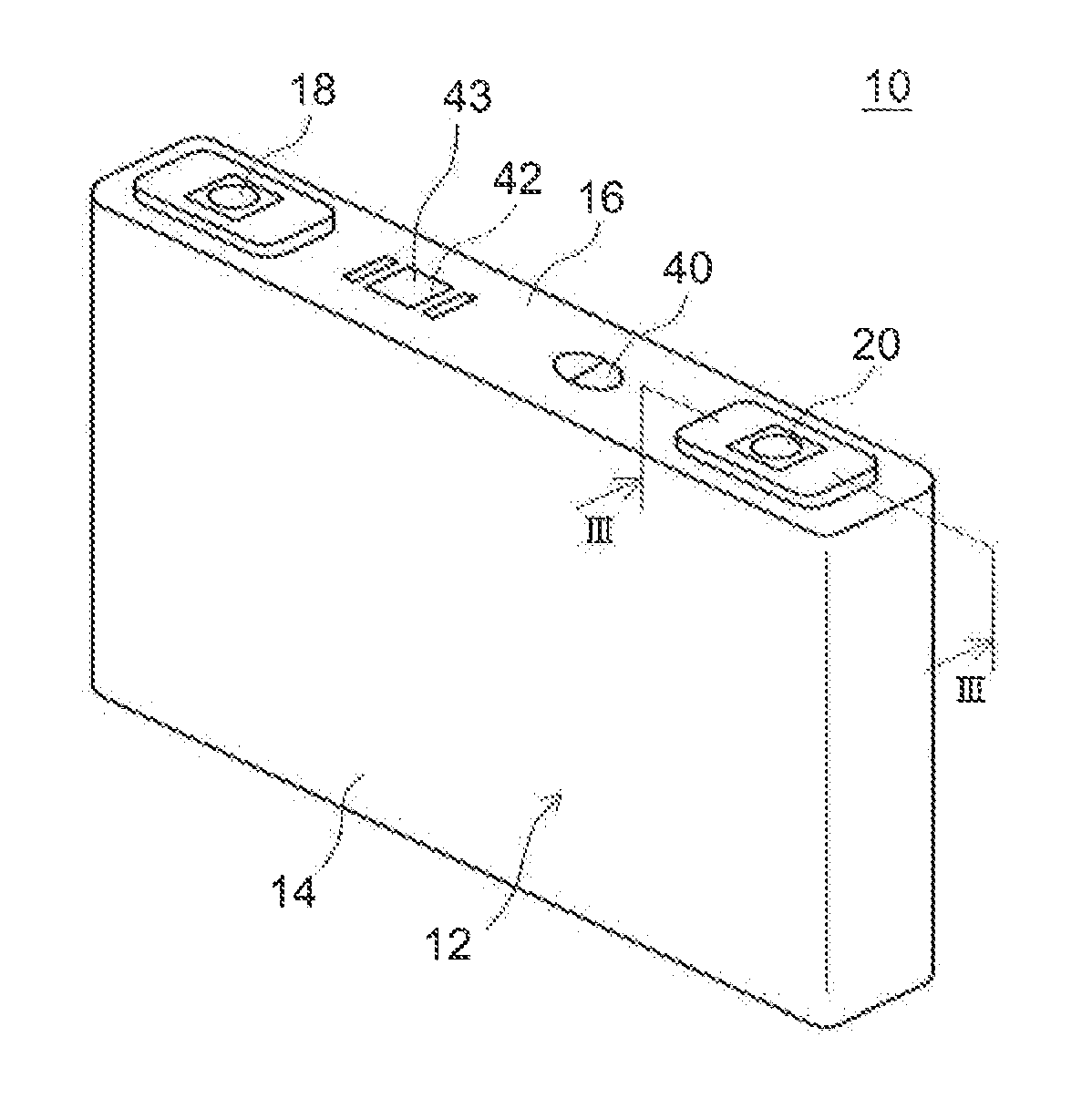
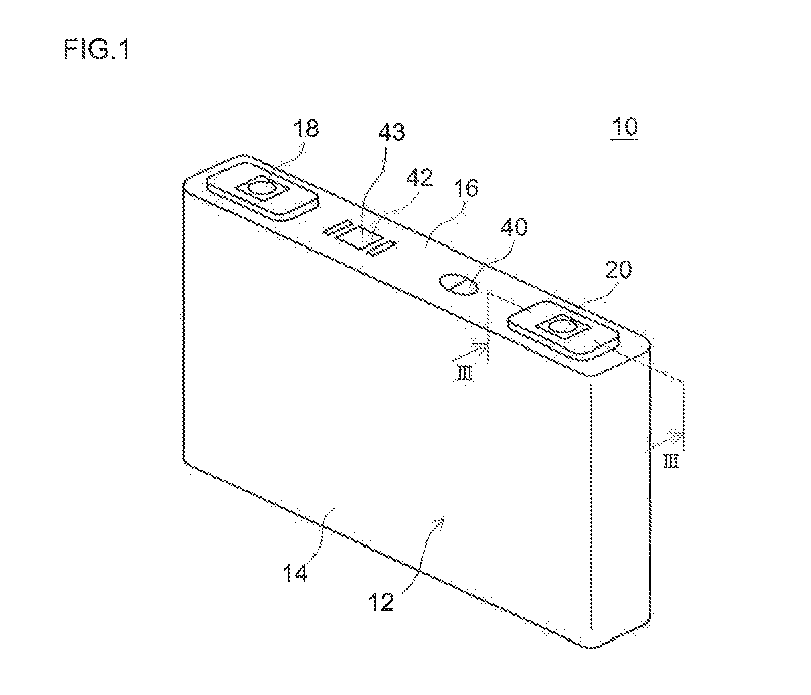
[0048]FIG. 1 shows a simplified perspective view illustrating the outer shape of a lithium-ion secondary battery according to the first embodiment. FIG. 2 shows an exploded perspective view illustrating the configuration of its current-blocking system. FIG. 3 shows a schematic cross-sectional view showing a close-up of the current-blocking system in cross section along III-III in FIG. 1.

[0049](Overall Constitution of Battery)

[0050]Lithium-ion secondary battery 10 according to the present embodiment is configured such that a flat wound electrode unit 50 as shown in FIG. 2 is housed in a battery case (i.e. exterior container) 12 shown in FIG. 1, along with a liquid electrolyte (electrolyte solution) not shown in the drawing.

[0051]Battery case 12 has a flat square shape corresponding to the shape of wound electrode unit 50. It is constituted with a box-shape (i.e. bottomed cuboid) main casing 14 having an opening at one end (corresponding to the top end of battery 10 in normal usage) a...

first example

of Modification

[0077]With reference to FIG. 16, here is described a modification example of lithium-ion secondary battery 10 according to the first embodiment (a lithium-ion secondary battery configured such that an annular groove 79 is provided to a thin portion 74 wherein a pressure-sensitive deformable portion 32 is securely joined to the thin portion of current collector at the inner side of the groove 79, and by snap-through deformation of the pressure-sensitive deformable portion, the thin portion 74 is caused to break off at the groove 79 while retaining the joint). In the example shown in FIG. 16, the thin portion 74 and groove 79 in current collector plate 72 in the first embodiment shown in FIG. 3 are omitted, and a current collector plate 72 having a uniform thickness is illustrated as shown in FIG. 16. By joining (e.g. welding) a pressure-sensitive deformable portion 32 to the central portion of the current collector plate 72, pressure-sensitive member (first conductive ...

second example

of Modification

[0080]As another example of modification of lithium-ion secondary battery 10 according to the first embodiment, instead of joining pressure-sensitive member 30 and current collector 70 together, it can be configured as shown in FIG. 17, such that pressure-sensitive deformable portion 32 of pressure-sensitive member (first conductive member) 30 directly contacts current collector (second conductive member) 70 (preferably, pressure-sensitive member 30 is elastically pushed against current collector 70) so as to attain conduction upon direct connection between pressure-sensitive member 30 and current collector 70 while pressure-sensitive deformable portion 32 is in the first state. In the example shown in FIG. 17, with the flat portion 32C of pressure-sensitive deformable portion 32 being elastically pushed against the top face of the central portion of current collector plate 72 in the first modification example, conduction between the two members is maintained. In the ...


PUM

PropertyMeasurementUnit
thicknessaaaaaaaaaa
heightaaaaaaaaaa
heightaaaaaaaaaa

Abstract

There is provided a sealed secondary battery whose current-blocking system yields little change in the actuation pressure even on long-term use. The sealed secondary battery comprises a current-blocking system 80 that is actuated by a pressure rise inside a battery case 12 to disconnect conduction path between an electrode and an electrode terminal. Current-blocking system 80 comprises a pressure-sensitive member having a pressure-sensitive deformable portion 32 that deforms from a first state via snap-through deformation to a second state upon a pressure rise inside battery case 12, and is configured to disconnect the conduction path by snap-through deformation of pressure-sensitive deformable portion 30.

Description

TECHNICAL FIELD[0001]The present invention relates to a sealed secondary battery. In particular, it relates to a sealed secondary battery comprising a current-blocking system actuated by an increase in the internal pressure.BACKGROUND ART[0002]Secondary batteries such as lithium secondary batteries and nickel-hydrogen batteries are preferably used as so-called portable power supplies in personal computers, mobile devices, etc., or as vehicle-driving power supplies. In particular, lithium secondary batteries that are lightweight and have high energy densities have become increasingly important as high output power supplies for use on vehicles such as electric automobiles, hybrid mobiles and the like (e.g. as power sources to drive motors connected to drive wheels of vehicles).[0003]Typical examples of such secondary batteries include a hermetic battery (sealed battery) obtainable by sealing an electrode unit having a positive electrode and a negative electrode along with an electroly...

Claims


Application Information

Patent Timeline
Patent Type & Authority Applications(United States)
IPC IPC(8): H01M2/34H01M10/34H01M50/528
CPCH01M2/345H01M2200/20H01M2220/20H01M10/34H01M50/528H01M50/578Y02E60/10H01M50/10
Inventor KOBAYASHI, KEIICHIROFUKUSHI, TAKANORI
Owner TOYOTA JIDOSHA KK
Why Eureka
Try Eureka