Manufacturing a generator rotor

a generator and rotor technology, applied in the direction of mechanical control devices, instruments, magnetic circuit shapes/forms/construction, etc., can solve the problems of high production cost, limited rotor diameters that rolling machinery can handle, and expensive and time-consuming post-production steps, so as to simplify the manufacturing process and improve the resin moulding process

Inactive Publication Date: 2015-06-18
SIEMENS AG
View PDF4 Cites 1 Cited by
  • Summary
  • Abstract
  • Description
  • Claims
  • Application Information

AI Technical Summary

Benefits of technology

[0031]According to an embodiment of the present invention, as an inner bonding material retaining structure an inner sheet is arranged between the radially inner fiber material and the auxiliary structure radially outer surface. The outer bonding material retaining structure may allow retaining the bonding material (in particular the resin) such that the bonding material is forced to stay in contact with the inner surfaces of the magnets. The inner sheet may form a portion of the bag (formed together with the outer sheet) for containing the entire bonding material and containing all magnets. Thus, when the outer sheet and the inner sheet are closed, all the permanent magnets including the applied bonding material is contained within the inside of the (e.g. annular) bag. The bag may then be evacuated (using a vacuum pump for removing air or other gases from the inside of the bag),...

Problems solved by technology

This machinery may be very expensive and at present there may be limits in relation to which rotor diameters the rolling machinery can handle.
Even further problems may be related to the very expensive a...

Method used


Image

  • Manufacturing a generator rotor
  • Manufacturing a generator rotor
  • Manufacturing a generator rotor

Examples


Embodiment Construction

[0054]The illustration in the drawings is in schematic form. It is noted that in different figures, similar or identical elements are provided with the same reference signs or with reference signs, which are different from the corresponding reference signs only within the first digit.

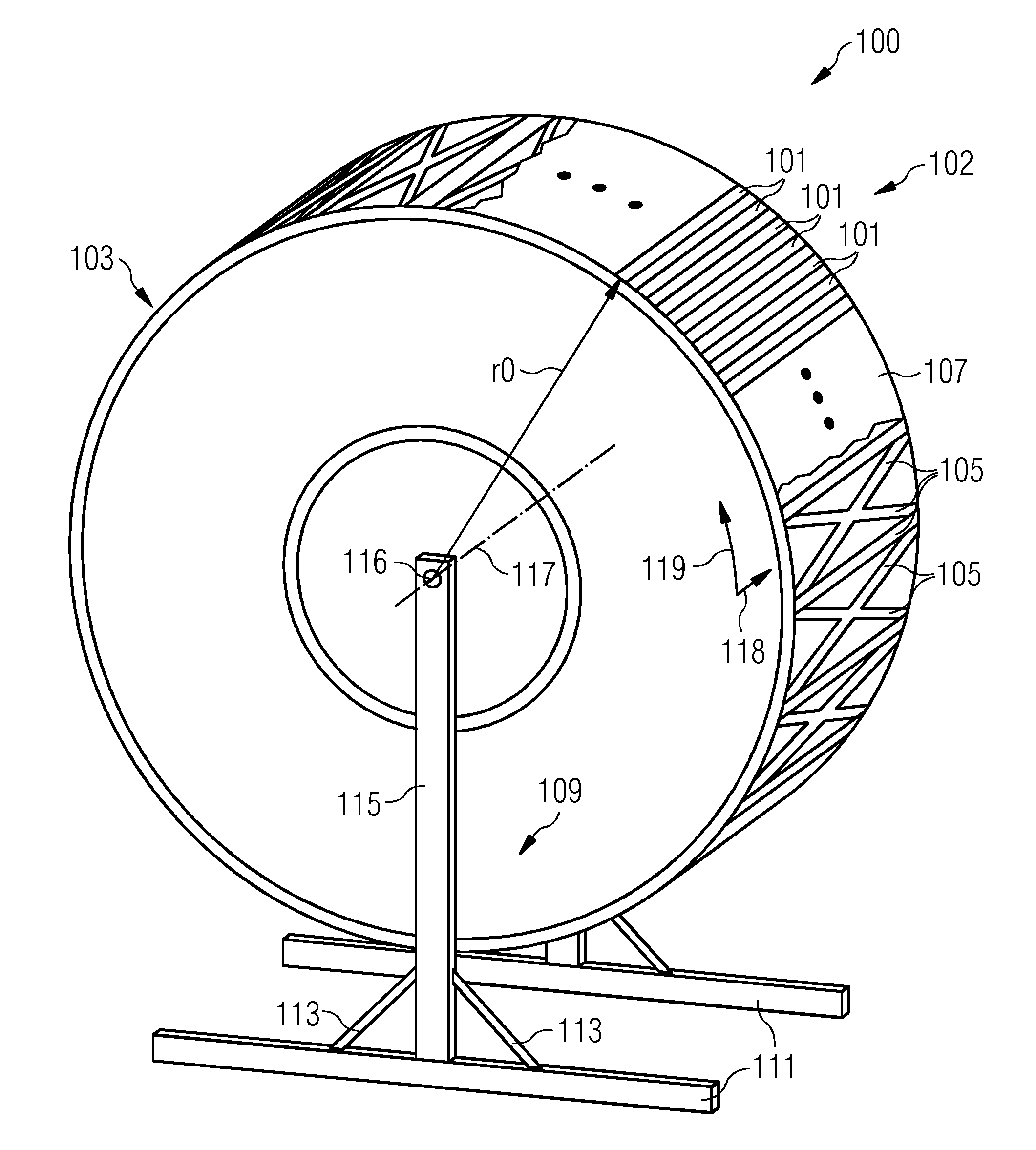
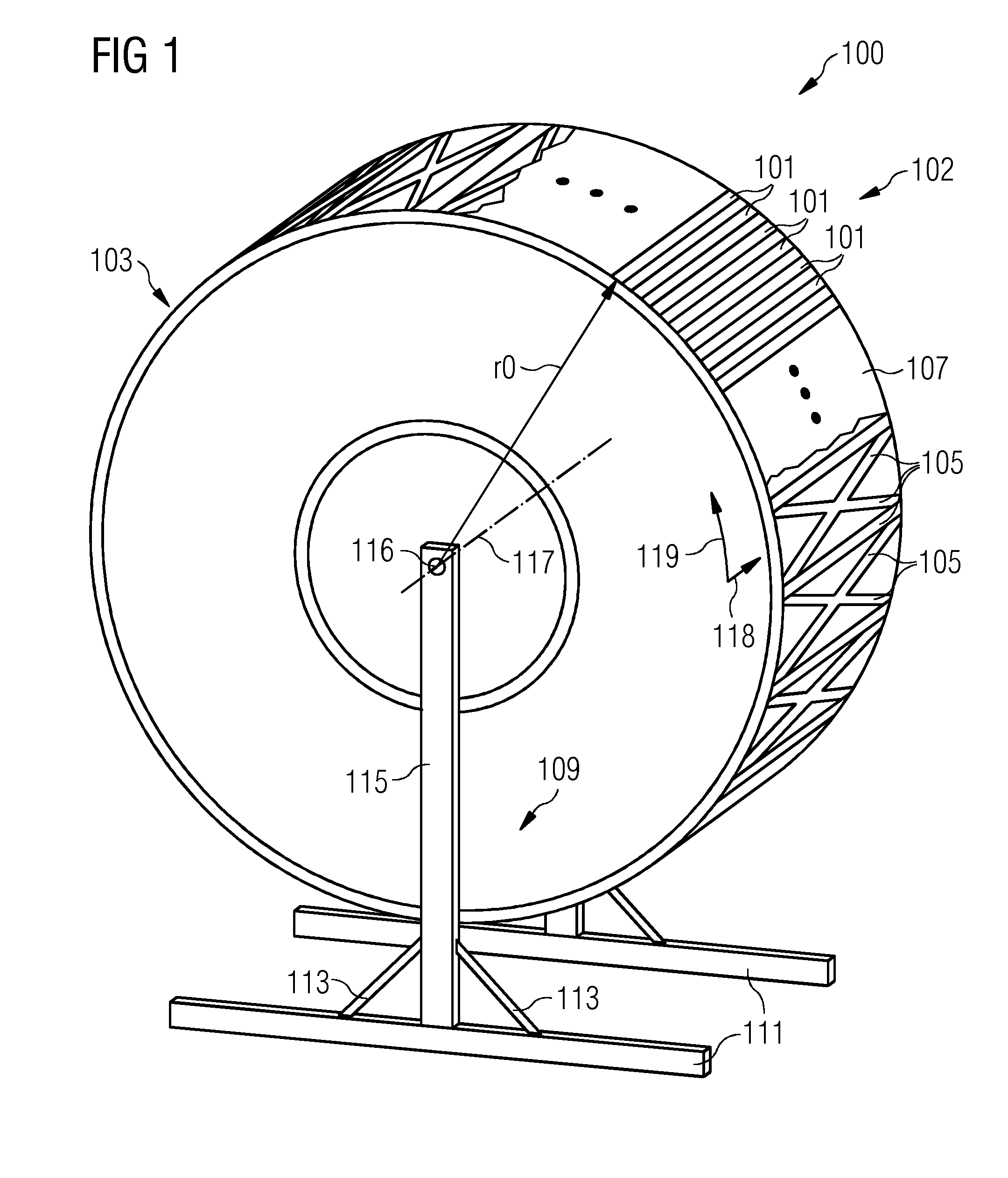
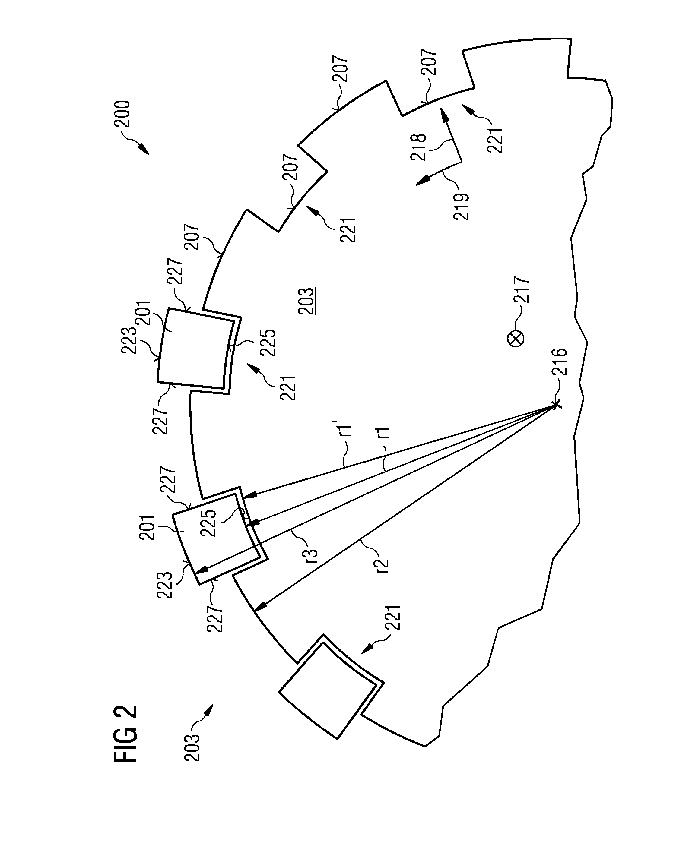
[0055]FIG. 1 illustrates a schematic perspective view of an arrangement 100 for manufacturing an outer rotor for an electrical generator according to an embodiment of the present invention in a state where already some permanent magnets 101 are releasably attached to the arrangement for manufacturing an outer rotor. The arrangement for manufacturing an outer rotor comprises a circular auxiliary structure 103 to which plural magnets are releasably attachable so that in FIG. 1 not visible radially inner surfaces of the magnets 101 are aligned to comply with an intended inner diameter of the rotor corresponding to two times an intended inner radius r0, as is illustrated in FIG. 1.

[0056]The annular (in part...


PUM

PropertyMeasurementUnit
Diameteraaaaaaaaaa

Abstract

A method for manufacturing an outer rotor for an electrical generator, the method including releasably attaching plural magnets at a circular auxiliary structure so that radially inner surfaces of the magnets are aligned to comply with an intended inner diameter of the rotor, and applying a bonding material at least in contact with radially outer surfaces of the magnets and circumferentially between magnets, in order to fix the aligned magnets in place is provided.

Description

CROSS-REFERENCE TO RELATED APPLICATION[0001]This application claims priority to EP 13198015.3, having a filing date of Dec. 18, 2013, the entire contents of which is hereby incorporated by reference.FIELD OF TECHNOLOGY[0002]The following relates to a method and an arrangement for manufacturing an outer rotor for an electrical generator and to an outer rotor for an electrical generator.BACKGROUND[0003]An electrical generator may be used in a wind turbine, wherein plural rotor blades drive a shaft which is connected to the rotor of the electrical generator, the rotor rotating relative to a stator comprising one or more windings. In particular, the generator may comprise a rotor having permanent magnets. In particular, the wind turbine may comprise a direct drive generator, i.e. a generator having a rotor which is connected to the same shaft to which plural rotor blades are connected. Such wind turbines thus do not comprise a gearbox for transforming a rotational speed of a main shaft ...

Claims


Application Information

Patent Timeline
IPC IPC(8): H02K15/03H02K1/27
CPCH02K1/2786H02K15/03H02K1/04H02K7/1838H02K1/2791
Inventor RASMUSSEN, MORTEN PILGAARD
Owner SIEMENS AG
Why Eureka
Try Eureka