
Tank

a technology for tanks and hydrocarbons, applied in the field of tanks, can solve the problems of increasing the load into and size of the mooring, generating motions unfavorable production operations, increasing the force, etc., and achieves the effect of reducing the external hydrostatic pressure and reducing the submerged

Inactive Publication Date: 2015-06-25
SEACAPTAUR IP
View PDF3 Cites 2 Cited by
  • Summary
  • Abstract
  • Description
  • Claims
  • Application Information

AI Technical Summary

Benefits of technology

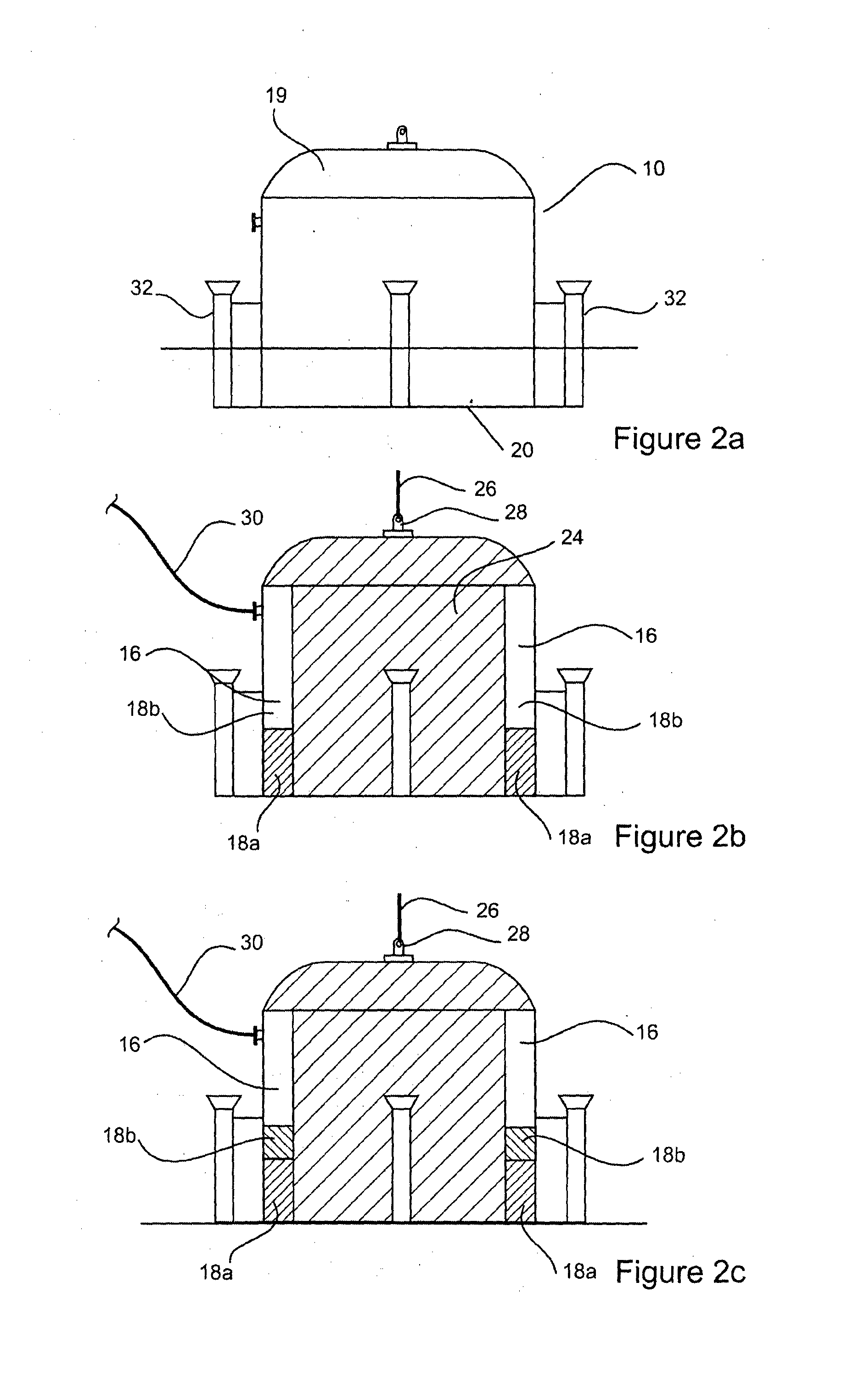
This patent describes a tank design for storing hydrocarbon liquids on the seabed. The tank has multiple compartments that can be selectively flooded or emptied to maintain pressure within the tank equal to the external pressure of the surrounding sea. This prevents the tank from exploding or bursting. The tank also includes a space between the inner and outer layers to reduce heat loss and facilitate thermal management of the stored hydrocarbons. The tank can be controlledly flooded and emptied to regulate its buoyancy and ascent to the water surface.

Problems solved by technology

A vessel on surface is subject to the forces of the sea, which generate motions unfavourable to production operations, and transfers loads into the mooring system.
The motions may be moderated by increasing the size of vessel, which in turn increases the forces, and increases the loads into and size of the moorings.
With motions so accommodated, there remains the problem of the many complex fluid / power / electronic signal interconnections between the subsea wells, and the vessel, which have to pass through the swivel.
This in turn impacts cost of building, installing and operating, consequently the minimum size of the resource, able to be commercially developed.

Method used


Image

  • Tank
  • Tank
  • Tank

Examples


Embodiment Construction

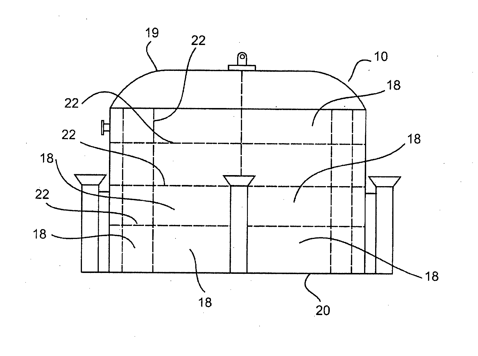
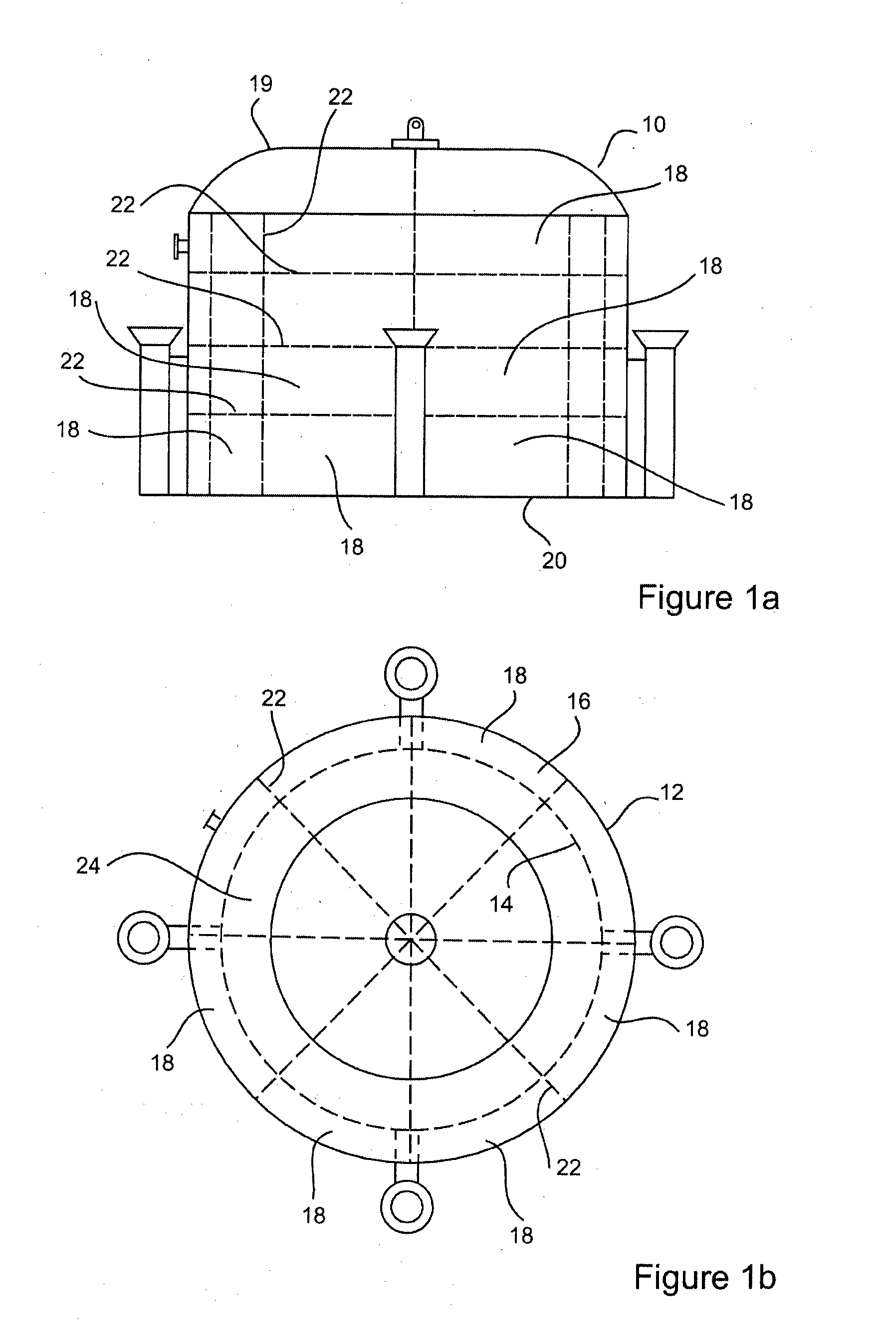
[0047]FIGS. 1a and 1b show a tank 10 in accordance with an embodiment of the invention. It should be noted that the FIGS. 1a and 1b are schematic only, and include phantom lines to show the internal structure of the tank.

[0048]Referring to FIGS. 1a and 1b, the tank 10 comprises an outer side wall 12 and an inner side wall 14 defining a hollow wall 16. The tank further comprises an upper plate 19, and a lower plate 20. The phantom lines shown in FIGS. 1a and 1b depict the inner side wall 14 as well as vertical and horizontal bulkheads 22 extending between the inner and outer side wall 12 and 14. The bulkheads 22 provide structural integrity to the hollow wall 16 defined by the inner and outer side walls 12 and 14.

[0049]The hollow wall 16 may be compartmentalized to form a plurality of compartments or chambers 18. The compartments 18 allow controlled flooding and evacuation of void space located between the outer and inner side walls 12 and 14, during sinking and recovery of the tank ...


PUM


Abstract

A tank for storage of hydrocarbon liquids on the seabed, being of double hull construction which is compartmented to form a plurality of chambers, such that the tank may be safely towed from its build location or shipyard, to offshore deployment location as marine warranty compliant vessel, having appropriate intact and damaged stability characteristics. There is also provided a method for deploying a tank for storage of hydrocarbon liquids on the seabed, the method comprising the step of towing the tank having un-ballasted storage areas and compartments to the location of deployment; flooding at least partially the storage area to achieve substantial neutral buoyancy of the tank to allow decent of the tank up to a submerged equilibrium; allowing decent of the tank to the seabed and injecting air into at least one compartment for maintaining equilibrium between the pressure applied by the surrounding sea and the pressure inside compartments and storage area.

Description

[0001]This application is a Continuation-in-Part of PCT / AU2013 / 000972, filed 29 Aug. 2013, which claims benefit of Serial No. 2012903826, filed 3 Sep. 2012 in Australia and which applications are incorporated herein by reference. To the extent appropriate, a claim of priority is made to each of the above-disclosed applications.TECHNICAL FIELD[0002]The present invention relates to hydrocarbon liquid storage offshore.[0003]The invention has been devised particularly, although not necessarily solely, in relation to subsea hydrocarbon liquid storage.BACKGROUND ART[0004]The following discussion of the background art is intended to facilitate an understanding of the present invention only. The discussion is not an acknowledgement or admission that any of the material referred to is or was part of the common general knowledge as at the priority date of the application.[0005]Typically, offshore hydrocarbon processing takes place at either: a fixed platform with wells on surface, or subsea w...

Claims


Application Information

Patent Timeline
IPC IPC(8): F17C1/00F17C5/02E04H7/02
CPCF17C1/007F17C5/02E04H7/02B65D88/78B65D90/028
Inventor ROBERTS, ALAN
Owner SEACAPTAUR IP
Learn More