Method and device for detecting a leakage in the area of at least one cooling device of a furnace and a furnace

a cooling device and leakage detection technology, which is applied in the field of leakage detection in the area of at least one cooling device of a furnace, can solve the problems of high mechanical and thermal stress, ingress of liquid coolant, and hazardous coolant ingress into the hot furnace chamber, and achieve the effect of rapid and reliable detection and special safety

Active Publication Date: 2015-07-02
SIEMENS VAI METALS TECH GMBH AUSTRIA +1
View PDF14 Cites 6 Cited by
  • Summary
  • Abstract
  • Description
  • Claims
  • Application Information

AI Technical Summary

Benefits of technology

[0046]Due to the rapid and reliable possibility for detecting the occurrence of a lea

Problems solved by technology

As a result, they are themselves exposed to high mechanical and thermal stresses.
For example, the area of the cooling device is repeatedly subject to cracking or leakages resulting in the ingress of liquid coolant into the hot furnace chamber.
A coolant ingress of this kind into the hot furnace chamber is hazardous since the coolant evaporates abruptly.
Depending upon the size of the leakage, an actual explosion may occur which can cause serious damage to the furnace and also endanger the life of the furnace operator.
It has been found that leakages in cooling devices are initially generally small and relatively little coolant enters the furnace chamber.
However, due to the high mechanical and thermal stress on the cooling device, the fine cracks that form and through which the coolant can escape, rapidly enlarge.
Existing systems for the early detection of leakages in cooling devices of furnaces d

Method used


Image

  • Method and device for detecting a leakage in the area of at least one cooling device of a furnace and a furnace
  • Method and device for detecting a leakage in the area of at least one cooling device of a furnace and a furnace
  • Method and device for detecting a leakage in the area of at least one cooling device of a furnace and a furnace

Examples


Embodiment Construction

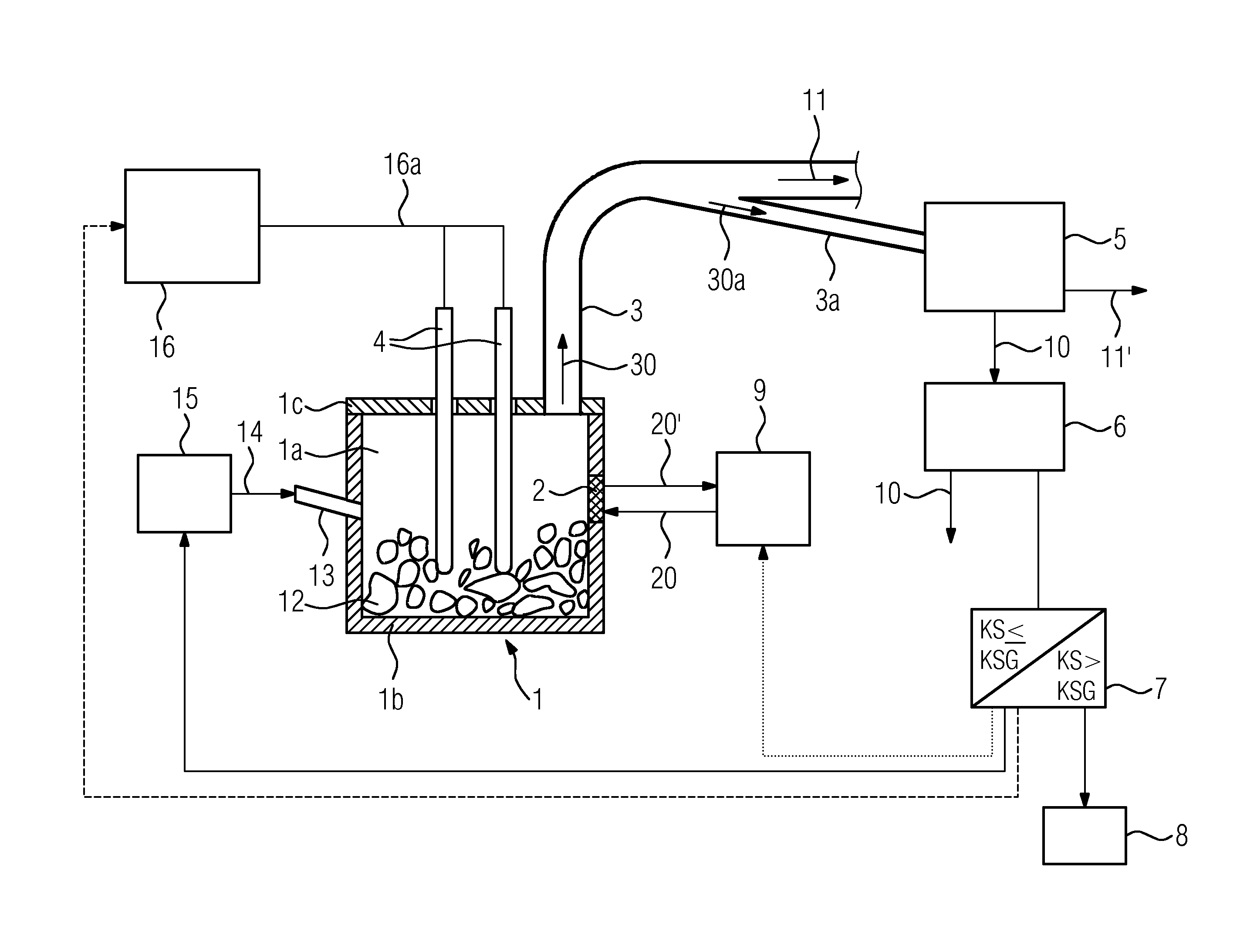
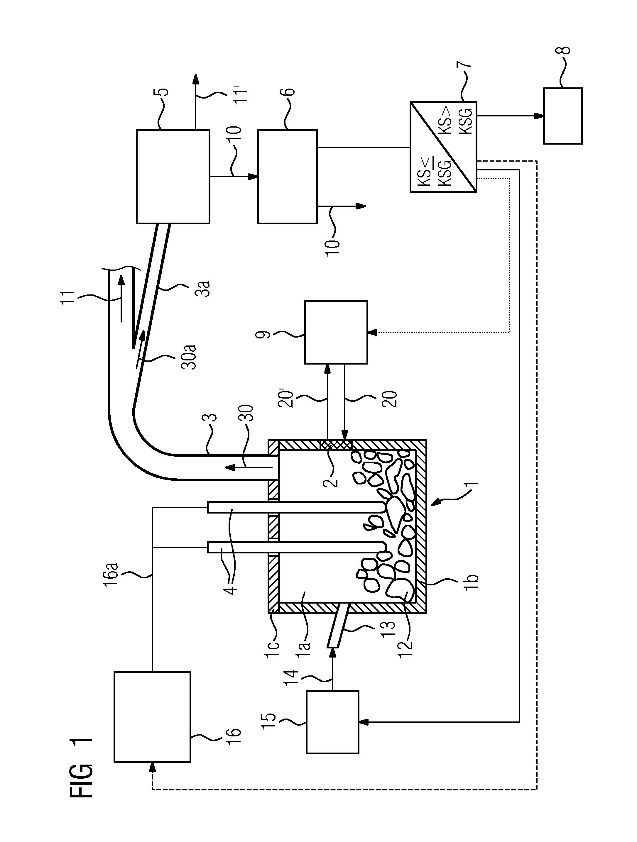
[0056]FIG. 1 shows a furnace 1 with a first device according to the invention. Here, the furnace 1 is an electric arc furnace for melting a material 12 in the form of metal scrap. It comprises a furnace vessel 1b and a furnace cover 1c, which together form a furnace chamber 1a, a cooling device 2 in a wall of the furnace vessel 1b, which is arranged in contact with the furnace chamber 1a, an exhaust gas removal line 3 for removing a stream of exhaust gas 30 from the furnace chamber 1a, a partial stream removal line 3a branching off from the exhaust gas removal line 3 and electrodes 4 that can be introduced into the furnace chamber 1a. A burner unit 13 is guided through the wall of the furnace vessel 1b and is supplied with fuel 14, here in the form of natural gas, via a fuel supply unit 15. The fuel 14 is burned in the burner unit 13 under the supply of air or oxygen (which is not shown for purposes of clarity). The electrodes 4 are connected via power supply leads 16a to a power su...


PUM

PropertyMeasurementUnit
Timeaaaaaaaaaa
Timeaaaaaaaaaa
Volumetric flow rateaaaaaaaaaa

Abstract

A method for detecting a leakage in the area of at least one cooling device of a furnace, wherein, in the event of a leakage, liquid coolant gets into a furnace chamber of the furnace from the at least one cooling device, and wherein a stream of exhaust gas is continuously removed from the furnace chamber over a period of time Z. The steps include dividing off a representative partial stream from the stream of exhaust gas during the period of time Z; condensing vaporous constituents contained in the partial stream; determining a stream of condensate obtained; comparing the stream of condensate obtained with a condensate-stream limit value; and indicating a leakage if the stream of condensate exceeds the condensate-stream limit value. Also a device for carrying out the method and a furnace with such a device are disclosed.

Description

CROSS-REFERENCE TO RELATED APPLICATIONS[0001]The present application is a 35 U.S.C. §§371 national phase conversion of PCT / EP2013 / 062146, filed Jun. 12, 2013, which claims priority of European Patent Application No. 12178854.1, filed Aug. 1, 2012, the contents of which are incorporated by reference herein. The PCT International Application was published in the German language.TECHNICAL FIELD[0002]The invention relates to a method for detecting a leakage in the area of at least one cooling device of a furnace, in particular an electric arc furnace, wherein in the event of a leakage, coolant from the at least one cooling device enters a furnace chamber of the furnace and wherein a stream of exhaust gas is removed from the furnace chamber over a period of time Z. The invention also relates to a device for carrying out the method and a furnace with a device of this kind.TECHNICAL BACKGROUND[0003]To protect the fireproof lining of a furnace from excessive thermal stress, cooling is frequ...

Claims


Application Information

Patent Timeline
IPC IPC(8): F27D21/00G01M3/02F27D11/08
CPCF27D21/00F27D2021/0071G01M3/02F27D11/08F27B3/24F27D1/12F27D19/00F27D21/04F27D2019/0015F27D2021/0078C21C2005/5288Y02P10/20F27B3/08
Inventor ABEL, MARKUSDORNDORF, MARKUSTRATNIG, MARKVAILLANCOURT, DENIS A.
Owner SIEMENS VAI METALS TECH GMBH AUSTRIA
Why Eureka
Try Eureka