
Methods and Apparatus for Sensor Diagnostics

a sensor and diagnostic technology, applied in the direction of instruments, solid-state devices, magnetic field measurement using galvano-magnetic devices, etc., can solve the problem of limited test opportunities to ensure that components are operating properly

Active Publication Date: 2015-07-02
ALLEGRO MICROSYSTEMS INC
View PDF13 Cites 29 Cited by
  • Summary
  • Abstract
  • Description
  • Claims
  • Application Information

AI Technical Summary

Benefits of technology

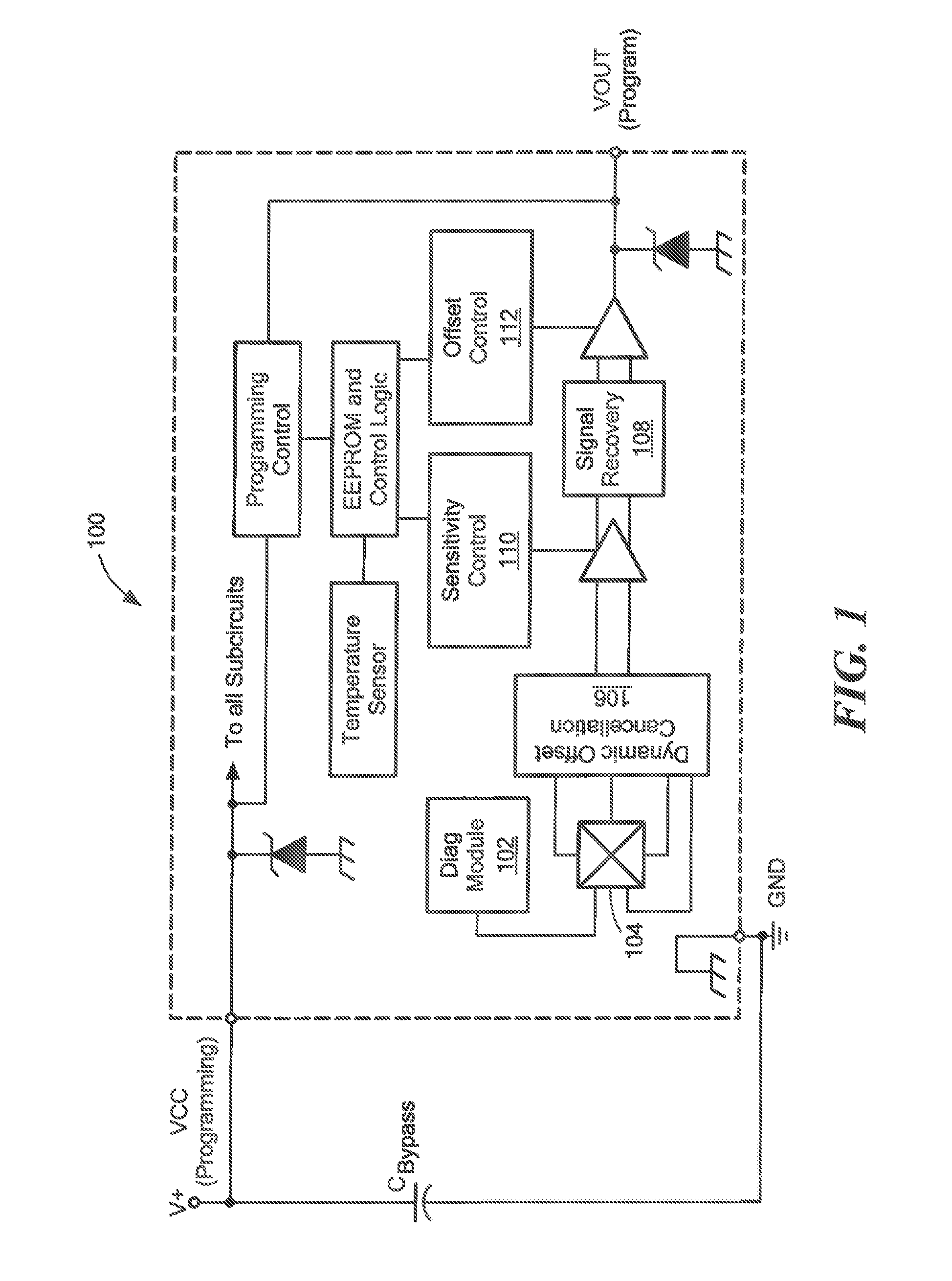
The invention relates to an integrated circuit that includes a magnetic sensing element and switches for monitoring the operation of a signal path. The integrated circuit can be used in a linear magnetic sensor or a magnetoresistive element. The switches are controllable to verify a gain of the signal path and can be placed in a region cutout from the leadframe to reduce eddy currents. The integrated circuit can also include an amplifier and a processor for monitoring and controlling the signal path. The technical effects of the invention include improved accuracy and reliability of magnetic sensing and reduced interference from eddy currents.

Problems solved by technology

However, after installation in a system or subsystem, such as an automobile, there are limited test opportunities to ensure that components are operating properly.

Method used


Image

  • Methods and Apparatus for Sensor Diagnostics
  • Methods and Apparatus for Sensor Diagnostics
  • Methods and Apparatus for Sensor Diagnostics

Examples


embodiment 800

[0088]As shown in FIG. 8, the device can sense whether the Fault pin has been pulled to about Vcc / 2, shown as VASILI, at the beginning of time interval tASILI in FIG. 7, and no magnetic field is detected by the Hall element. In the illustrated embodiment 800, a signal from the Hall element is provided to first and second comparators 802, 804, which have respective reference voltages defined by the values of R1, R2, and R3 that determine what is considered ‘zero’ magnetic field. That is, the magnetic field should be less than some value. In one embodiment, resistor R2 is adjustable for setting the comparator reference voltages, e.g., a programmable window comparator. The outputs of the comparators 802, 804 are provided to an input of an AND gate 806, of which the output is provided to a clocked counter 808. The Fault pin voltage is input to third and fourth comparators 810, 812, which have respective reference voltages determined by the values of R4, R5, R6. The comparator 810, 812 o...

embodiment 1000

[0099]An alternate embodiment 1000 of testing the window comparators is shown in FIG. 10 that tests in parallel instead of sequentially. The logic gates G1-3 and comparators CP1, CP2 must function correctly for the ASIL test to pass. During normal operation only the NAND gate G3 following the comparators CP1, CP2 is used in the Fault signal path. During normal Fault detection operation the window references RefH and RefL are used as thresholds to detect a fault condition. In ASIL test mode after the required time tASILI described above verifies that an ASIL test is being requested, the references are switched to TestRefH and TestRefL. Also, at that time, a MUX is switched to detect the alternate logic path. TestRefH and Test RefL need only be of a value that the comparators should trip as described above. In one embodiment, there is a cross connect of the two normal operation references such that TestRefH=RefL and TestRefL=RefH. This ensures that the comparators CP1, CP2 have output...


PUM


Abstract

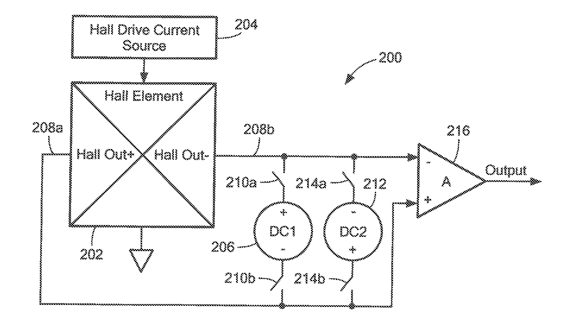
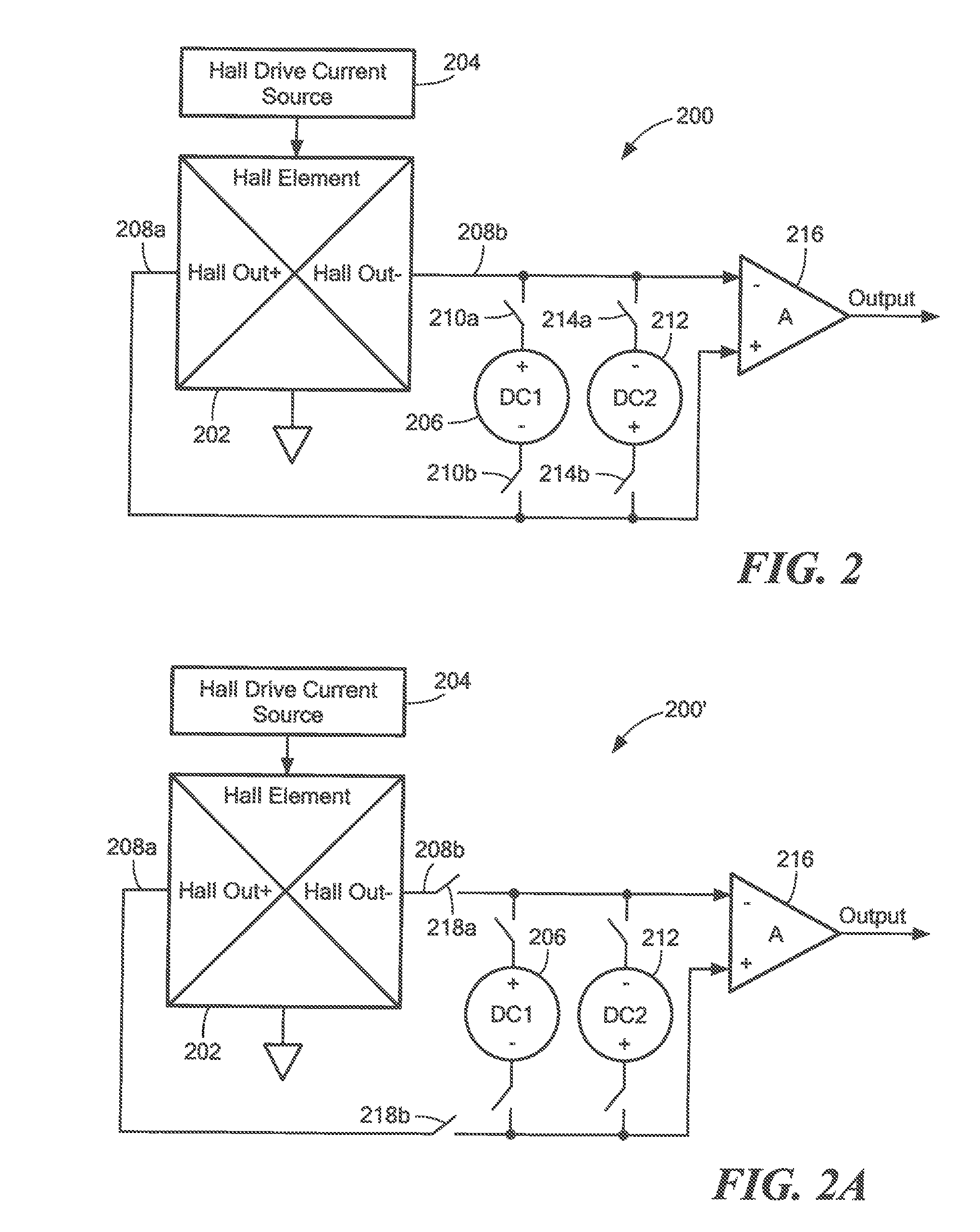
Methods and apparatus for providing an integrated circuit having a drive current source, a magnetic sensing element coupled to the drive current source, the magnetic sensing element having first and second differential outputs, and first and second current elements to provide respective currents in relation to the drive current source, wherein the first current element is coupled to the first differential output and the second current element is coupled to the second differential output. In illustrative embodiments, an IC output can output a voltage corresponding to the currents of the first and second current elements.

Description

CROSS REFERENCE TO RELATED APPLICATIONS[0001]The present application claims the benefit of U.S. Provisional Patent Application No. 61 / 920,827, filed on Dec. 26, 2013, which is incorporated herein by reference.BACKGROUND[0002]As known in the art, there are many safety critical applications for magnetic sensor integrated circuits (ICs). There are a variety of specifications directed to improving functional safety and achieving higher overall quality levels and lower field failure rates. For example, test modes for major functional parameters of an IC allow customers to implement test functionality prior to insertion on a printed circuit board, for example. However, after installation in a system or subsystem, such as an automobile, there are limited test opportunities to ensure that components are operating properly.SUMMARY[0003]In one aspect of the invention, an integrated circuit comprises: a magnetic sensing element having differential first and second outputs and an input, the inp...

Claims


Application Information

Patent Timeline
Patent Type & Authority Applications(United States)
IPC IPC(8): G01R33/00G01R33/07G01R33/09G01R35/00
CPCG01R33/0023G01R33/09G01R33/07G01R35/00G01R33/091G01R31/2829H01L2224/48091H01L2224/48247H01L2224/48257H01L2924/181H01L2924/00014H01L2924/00012G01R31/2884G01R31/3187G01R33/072G01R35/005G01R33/00G01R33/02
Inventor MILANO, SHAUN D.EL BACHA, GEORGESDOOGUE, MICHAEL C.HAAS, DAVID J.DELMAIN, GREGORYGABOURY, MICHAELTAYLOR, WILLIAM P.
Owner ALLEGRO MICROSYSTEMS INC
Learn More