
Band-pass filter

Active Publication Date: 2015-07-02
INST OF PHYSICS - CHINESE ACAD OF SCI +3
View PDF3 Cites 2 Cited by
  • Summary
  • Abstract
  • Description
  • Claims
  • Application Information

AI Technical Summary

Benefits of technology

The patent text describes a new type of filter that can reduce the loss of signal when sending microwave signals through a waveguide. This is achieved by using a special design with a conductive insert that helps to redistribute the current in the waveguide walls, which in turn reduces the resistance and loss of signal. Overall, this new design improves the quality of microwave signals and allows for better performance in applications that require high-quality signal transmission.

Problems solved by technology

However, the specified dielectrics are fragile and are easy to be destroyed in cooling-heating cycles of filter when the specified dielectrics are in close mechanical contact with the filter body.
The reason is that temperature gradients caused during cooling in the filter body introduce unacceptable mechanical stresses in the dielectric plate.

Method used


Image

  • Band-pass filter
  • Band-pass filter
  • Band-pass filter

Examples


Embodiment Construction

[0029]Exemplary embodiments of the present invention will be described hereinafter in detail with reference to the attached drawings, wherein the like reference numerals refer to the like elements. The present invention may, however, be embodied in many different forms and should not be construed as being limited to the embodiment set forth herein; rather, these embodiments are provided so that the present invention will be thorough and complete, and will fully convey the concept of the disclosure to those skilled in the art.

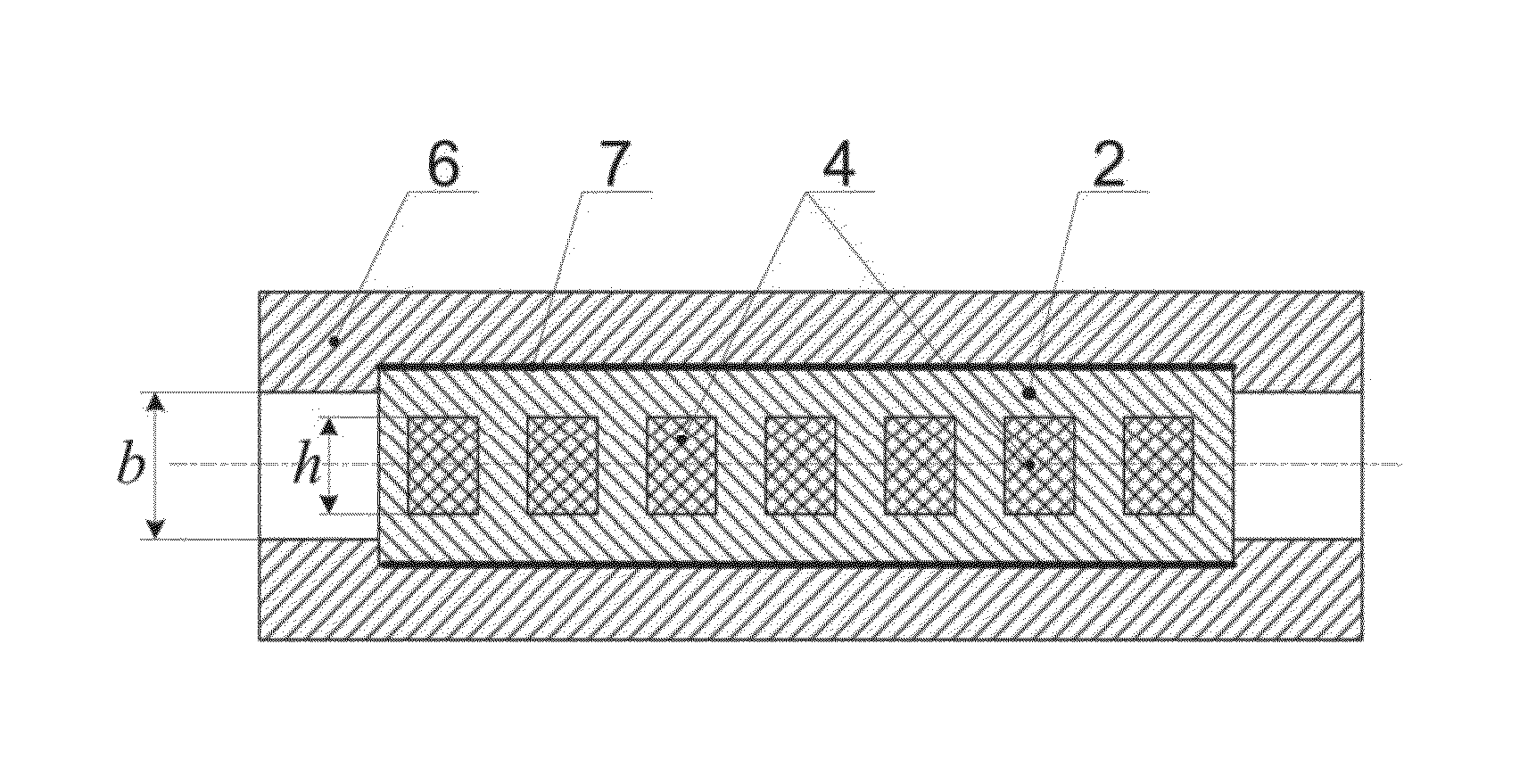
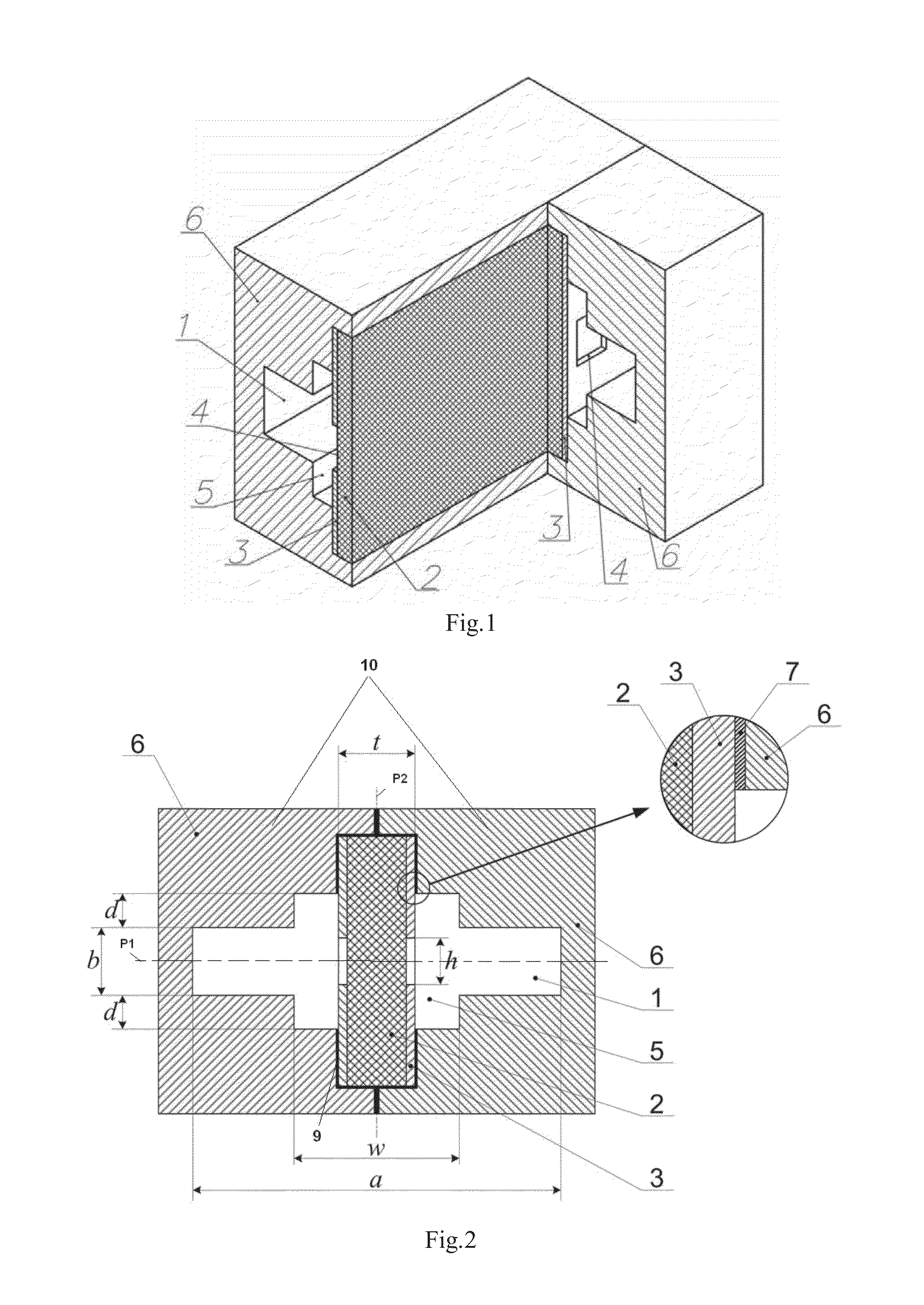
[0030]As shown in FIGS. 1 and 2, a band-pass filter comprises a rectangular waveguide 1 of a×b cross-section and a dielectric plate (or substrate) 2. Identical HTS films 3 with a number of windows 4 of the same height are placed symmetrically relative to a bisecting plane P1 of the rectangular waveguide in the height direction. The windows 4 have different lengths and are spaced from each other by different distances. Specific dimensions of the windows 4 are det...


PUM


Abstract

Band-pass filter having a body comprising a rectangular waveguide and a dielectric insert comprising a dielectric plate and a high temperature superconductive film in line with a number of rectangular windows of the same height. The waveguide has a×b cross-section, a being length of the wide wall and b the length of the narrow wall. Each wide wall has a fixing groove at the central portion and a rectangular recess in the fixing groove. The dielectric plate has two ends in the fixing grooves and is symmetric with a perpendicular bisecting plane of the wide wall. The rectangular recess is symmetric to the perpendicular bisecting plane and has same length as the waveguide, with its width w satisfies t<w<a / 2, and depth d satisfies d<λ / 4, t being total thickness of the dielectric plate and the high temperature superconductive film, and λ the wavelength of the central frequency of the pass-band of the band-pass filter.

Description

CROSS-REFERENCE TO RELATED APPLICATION[0001]The subject application claims the benefit of Ukrainian Patent Application No. a 2013 15299 filed on Dec. 26, 2013 in the Patent Office of Ukraine, the whole disclosure of which is incorporated herein by reference.BACKGROUND OF THE INVENTION[0002]1. Field of the Invention[0003]The present invention relates to the microwave technique, particularly, a band-pass filter which can be used in cryo-electronic units at the front end of a receiver used in radio telescopes and satellite communication lines.[0004]2. Description of the Related Art[0005]Band-pass filters that are installed at the input of low-noise amplifiers (LNA) are designed to provide electromagnetic compatibility of radio electronic facilities, i.e., to protect input circuits of a highly sensitive receiver from electromagnetic radiation outside the operating bandwidth. Currently, transistor LNA are widely used and replace the previously developed parametric and quantum amplifiers ...

Claims


Application Information

Patent Timeline
IPC IPC(8): H01P1/20
CPCH01P1/2002H01P1/207H01P1/2016H01P5/1007
Inventor SUN, LIANGWANG, XUWANG, JIAWU, YUNHE, YUSHENGLI, HONGHUANG, JIANGMINGLUO, SHENGSKRESANOV, VALERIIBARANNYK, OLEKSANDRGLAMAZDIN, VOLODYMYRZOLOTAREV, VOLODYMYRNATAROV, MYHAYLOCHERPAK, MYKOLASHUBNYJ, OLEKSANDR
Owner INST OF PHYSICS - CHINESE ACAD OF SCI
Learn More