
Refrigeration cycle device

a refrigerant cycle and battery technology, which is applied in the field of refrigerant cycle devices, can solve the problems that the refrigerant cycle devices of patent document 1 cannot appropriately adjust the temperature of the battery in a temperature range lower, and the battery (electric cell) mounted on the electric vehicle or hybrid vehicle needs warming up as its discharge efficiency is reduced, so as to achieve the effect of reducing the size of the accumulator and large fluctuations in the flow ra

Active Publication Date: 2015-07-09
DENSO CORP
View PDF4 Cites 28 Cited by
  • Summary
  • Abstract
  • Description
  • Claims
  • Application Information

AI Technical Summary

Benefits of technology

The present disclosure relates to a refrigeration cycle device that can adjust the temperature of a battery in a vehicle interior. The device includes a high-stage side decompressor that can change its opening degree, allowing easy adjustment of the refrigerant decompressed by the decompressor. This ensures quick and accurate adjustment of the battery temperature within an appropriate range. Even if the flow rate of the refrigerant fluctuates due to the adjustment of the decompressor, an accumulator can prevent liquid compression of the compressor, reducing the size of the accumulator required. The device also includes an air heating-warming up mode and an air heating-non-temperature adjustment mode to control the battery temperature without affecting the air temperature. This prevents liquid-phase refrigerant from being retained in the battery heat exchanger and ensures efficient operation of the refrigeration cycle device.

Problems solved by technology

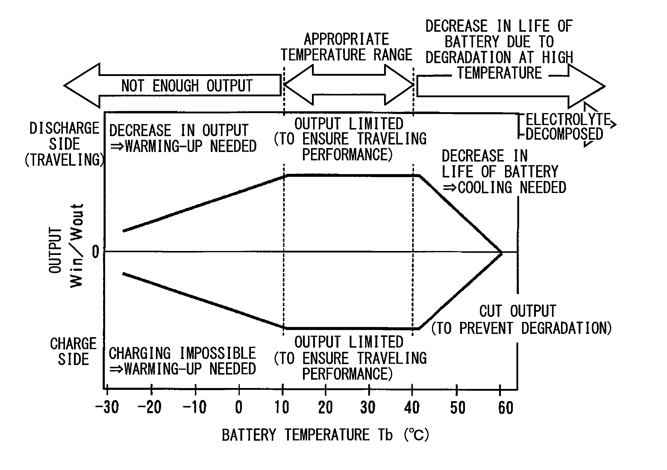
On the other hand, a battery (electric cell) mounted on the electric vehicle or hybrid vehicle needs warming-up as its discharge efficiency is reduced at low temperature, but might be degraded when being warmed up at unnecessarily high temperature only to become unusable.
In other words, the refrigerant cycle device of Patent Document 1 cannot appropriately adjust the temperature of the battery in a temperature range lower than that of the air.

Method used


Image

  • Refrigeration cycle device
  • Refrigeration cycle device
  • Refrigeration cycle device

Examples


first embodiment

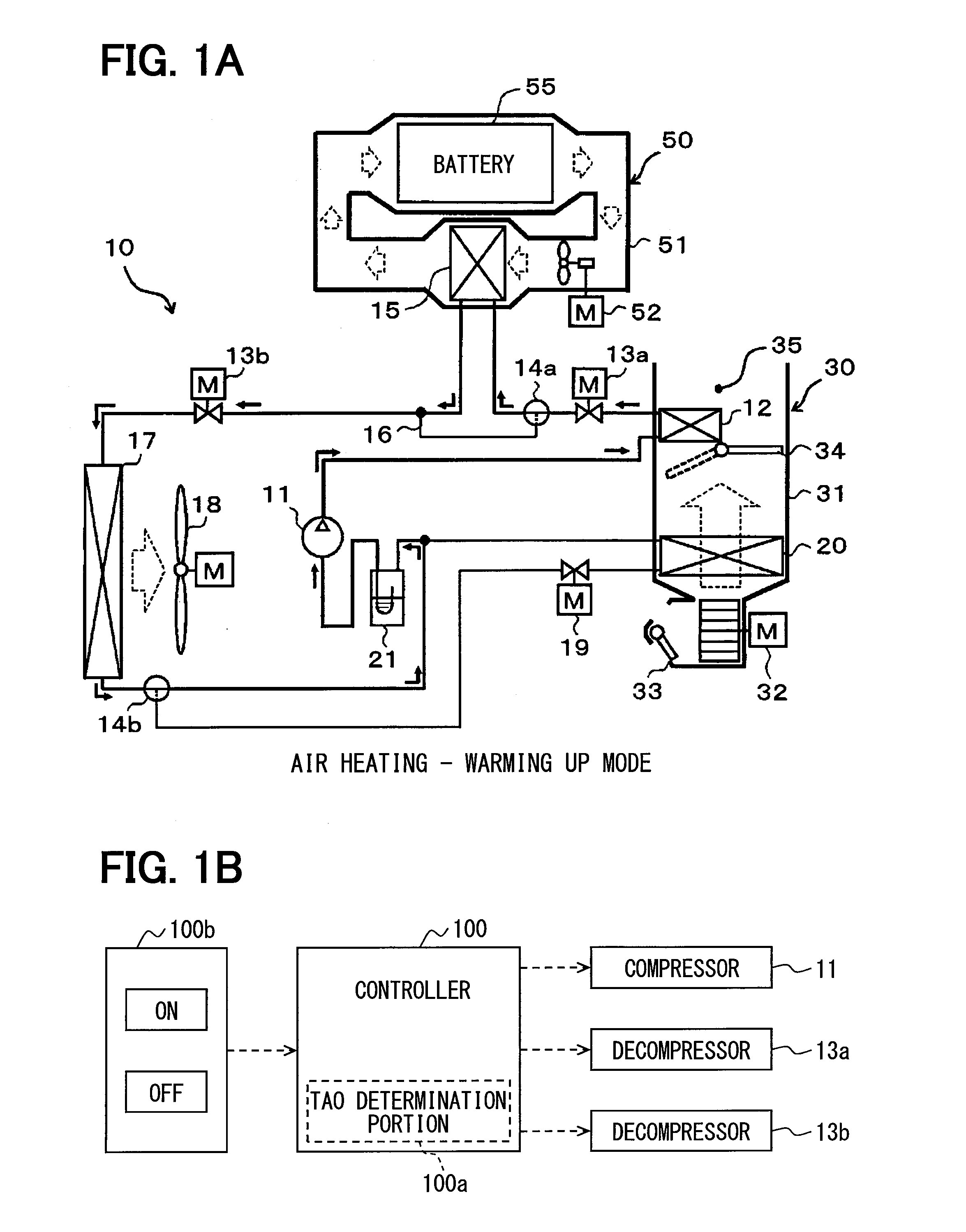
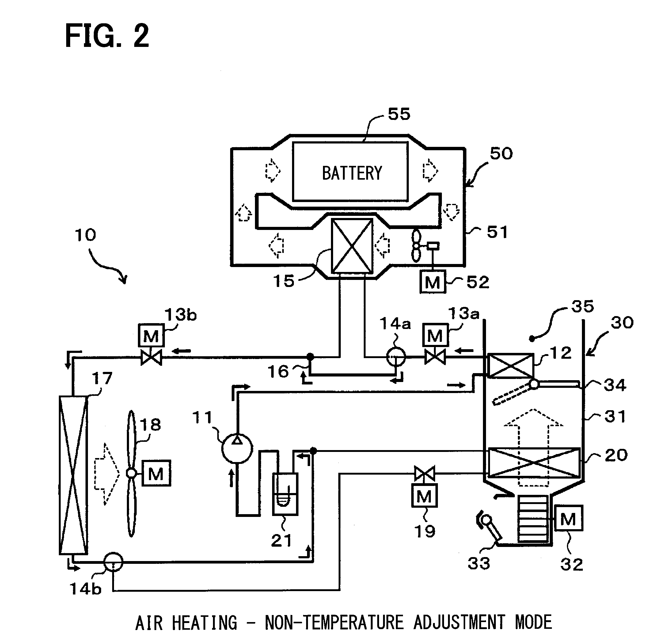
[0038]A first embodiment of the present disclosure will be described below with reference to FIGS. 1A to 9. In this embodiment, a refrigeration cycle device 10 is applied to an electric vehicle that is designed to obtain a driving force for traveling from a traveling electric motor. Further, in the electric vehicle, the refrigeration cycle device 10 can be used to control air conditioning (air cooling and heating) of a vehicle interior, and also to adjust the temperature (warming-up) of a battery 55 which serves as an electric storage device for storing therein electric power to be supplied to the traveling electric motor.

[0039]Thus, the refrigeration cycle device 10 performs a function of adjusting the temperature of air for a vehicle interior to be blown into a vehicle compartment as a space to be air conditioned, and another function of heating air for the battery to be blown toward the battery 55. In other words, the refrigeration cycle device 10 can adjust the temperatures of a...

second embodiment

[0153]Although the first embodiment has described the refrigeration cycle device that can switch between the warming-up mode of warming up the battery 55 and the non-temperature adjustment mode of not warming up the battery 55, this embodiment will describe the refrigeration cycle device 10 that can further perform a cooling mode operation for cooling the battery 55.

[0154]First, the entire configuration of the refrigeration cycle device 10 of this embodiment will be described below using FIGS. 10 and 11. Referring to FIGS. 10 and 11, the same or equivalent part as that in the first embodiment is designated by the same reference numeral. The same goes for the following figures. FIGS. 10 and 11 show the flows of the refrigerant in the air heating-cooling mode as well as in the air cooling-cooling mode by solid arrows.

[0155]As can be seen from FIGS. 10 and 11, as compared to the structure of the first embodiment, in the refrigeration cycle device 10 of this embodiment, a first connecti...

third embodiment

[0200]In the example described in the first embodiment, in the air heating-warming up mode, the refrigerant discharge capacity of the compressor 11 is controlled to cause the air temperature TAV to approach the target air temperature TAO, and the opening degree of the high-stage side expansion valve 13a is controlled to maintain the temperature of the battery 55 within the reference temperature range.

[0201]In such control of the air heating-warming up mode, first, the heat included in the refrigerant discharged from the compressor 11 is used to heat the air for the interior so as to be capable of achieving the sufficient heating of the vehicle interior, and then the remaining heat is used to heat the air for the battery. That is, the air heating-warming up mode described in the first embodiment can be expressed as an operation mode in which heating of the vehicle interior is prioritized over the warming-up of the battery 55 (namely, heating priority mode).

[0202]For example, on a tra...


PUM


Abstract

A refrigeration cycle device includes an air heat exchanger that heats air to be blown into an interior of a vehicle compartment using refrigerant discharged from a compressor, a high-stage side expansion valve decompressing the refrigerant flowing out of the air heat exchanger, and a battery heat exchanger that heats air to be blown to a battery using the refrigerant decompressed by the high-stage side expansion valve. In an air heating-warming up mode of heating the air for the interior and the air for the battery, a refrigerant discharge capacity of the compressor is controlled such that an air temperature for the interior approaches a target air temperature, and an opening degree of the high-stage side expansion valve is controlled such that a battery temperature becomes within a predetermined reference temperature range. A selector switch allows a passenger to select which operation of air conditioning or warming-up is prioritized.

Description

[0001]The application is based on Japanese Patent Applications No. 2012-159326 filed on Jul. 18, 2012, and No. 2013-116717 filed on Jun. 3, 2013, the contents of which are incorporated herein by reference in its entirety.FIELD OF THE INVENTION[0002]The present disclosure relates to a refrigeration cycle device for adjusting temperatures of a plurality of temperature adjustment objects.BACKGROUND ART[0003]In a related art, for example, Patent Document 1 discloses a vapor compression refrigeration cycle device that is adapted to adjust temperatures of a plurality of temperature adjustment objects (fluids to be temperature adjustment). The refrigeration cycle device disclosed in Patent Document 1 is mounted on a fuel cell vehicle. In order to achieve heating of an interior of a vehicle and warming up a fuel cell, the refrigeration cycle device is designed to heat different kinds of fluids to be temperature adjustment, including air (blast air) to be blown into the vehicle interior and ...

Claims


Application Information

Patent Timeline
IPC IPC(8): B60H1/00B60H1/22
CPCB60H1/00278B60H1/22B60H1/00885F25B1/00F25B41/24F25B41/20B60H1/3213B60H2001/3258B60H2001/3275H01M10/615H01M10/663H01M10/6563F25B6/04F25B2600/2513B60L1/003B60L1/006B60L15/20B60L2240/34B60L2240/421B60L2240/545B60L2240/662Y02T90/16Y02T10/72B60H2001/00307B60L50/52B60L58/26B60L58/27B60L50/64Y02T10/64Y02T10/70Y02E60/10F25B41/39
Inventor INOUE, SEIJITAKEUCHI, MASAYUKIYAMANAKA, TAKASHI
Owner DENSO CORP
Learn More