
Phosphor sheet

Active Publication Date: 2015-07-16
DEXERIALS CORP
View PDF0 Cites 31 Cited by
  • Summary
  • Abstract
  • Description
  • Claims
  • Application Information

AI Technical Summary

Benefits of technology

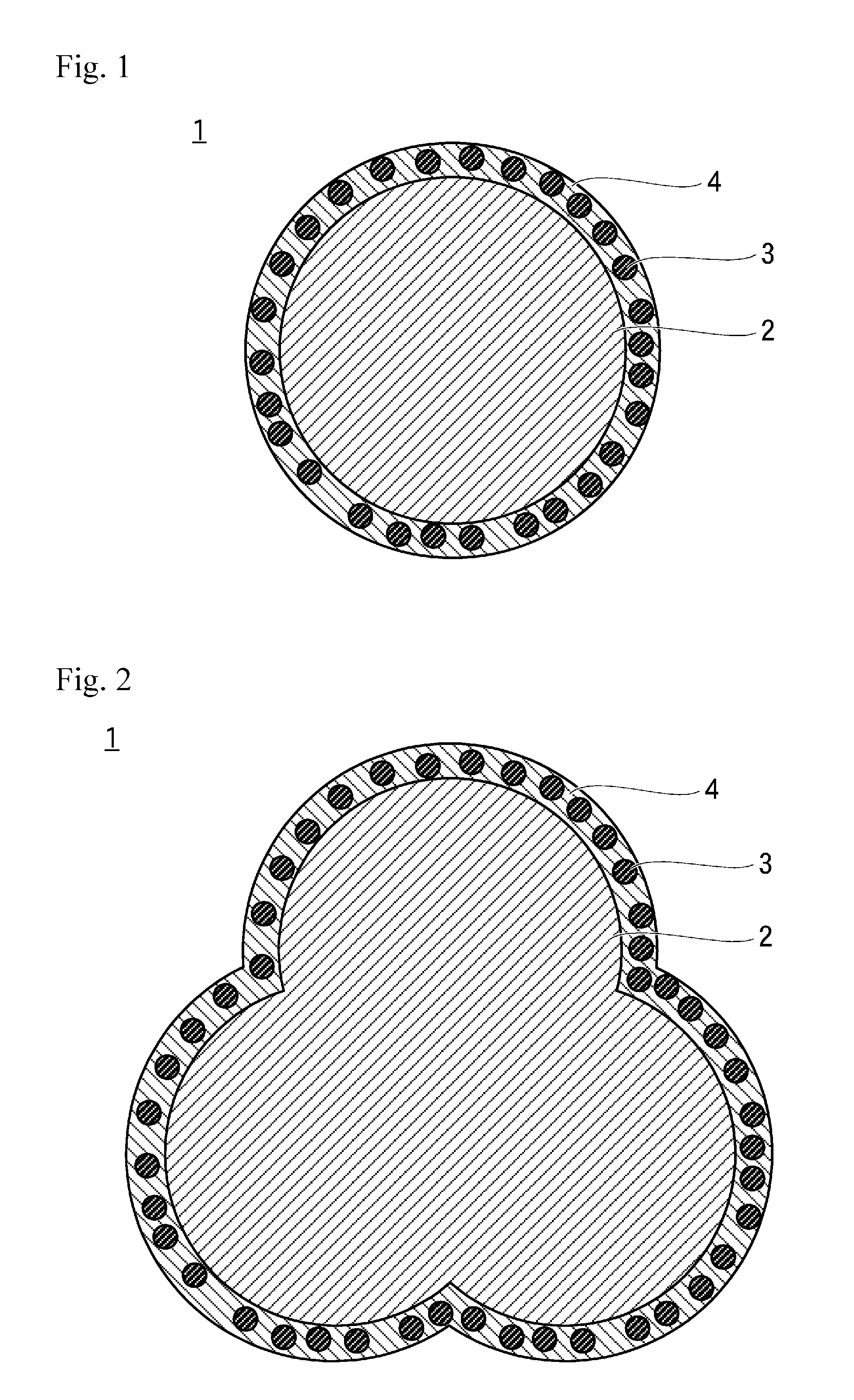
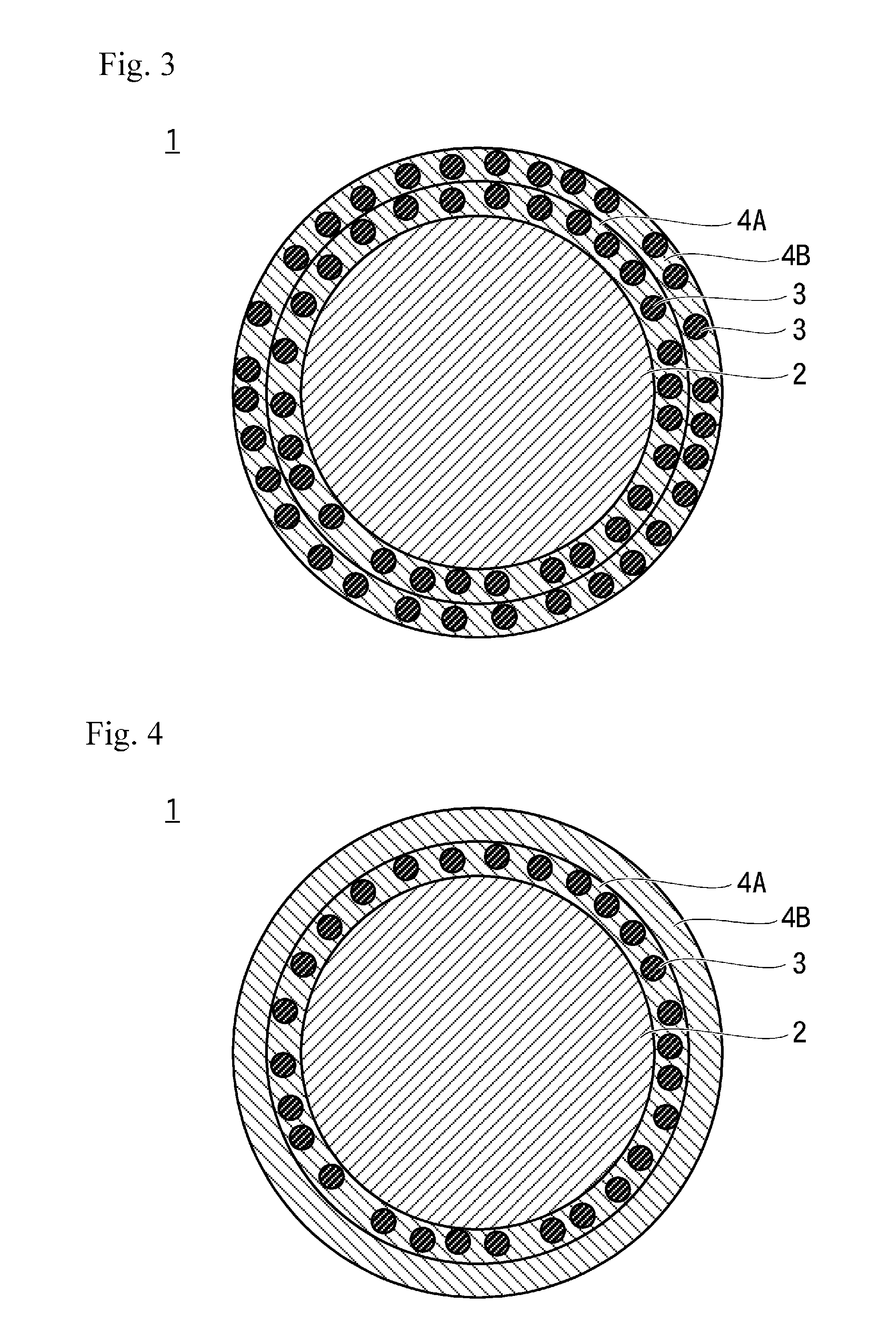
The patent text describes a way to prevent the fading or corrosion of a type of light-emitting material called a sulfide phosphor particle. This is done by coating the particle with a film made of silicon dioxide and containing metal oxide powders. This results in a more stable and durable material, with improved performance in applications that require light emission.

Problems solved by technology

Some phosphor particles are fragile against oxygen or water vapor.
When the phosphor particles are exposed to oxygen or water vapor, their properties deteriorate to cause luminance or chromaticity unevenness.
For example, a sulfide phosphor particle easily deteriorates by an environment, such as, water or oxygen and significantly deteriorates particularly under high-temperature and high-humidity conditions.
Deterioration of the sulfide phosphor particle reduces the lifetime of an LED element because a sulfur component in the phosphor particles itself causes corrosion of a metal at a current-carrying portion in the LED element to induce a decrease in light extraction efficiency in the LED element, break of an energization portion, and the like.
However, even when the surface of the phosphor particle is coated as described in Patent Literature 4, chromaticity shift or corrosion due to deterioration of the sulfide phosphor particle cannot be suppressed sufficiently.
Furthermore, in the technologies of Patent Literatures 5 to 7, the phosphor particle itself is not protected, and deterioration of the phosphor particle during long-term use is unavoidable.

Method used


Image

  • Phosphor sheet
  • Phosphor sheet
  • Phosphor sheet

Examples


example 1

[0138]10 g of phosphor particles for red ((Ba,Sr)3SiO6:Eu), 80 g of ethanol, 5 g of pure water, and 6 g of 28% aqueous ammonia are added into a resin container (PE), a magnetic stirrer was loaded thereinto, and the mixture is stirred for 10 minutes in a thermostatic chamber at 40 degrees Celsius. After that, 5 g of tetraethoxysilane and 35 g of ethanol were added thereto. The time when the addition is completed is defined as 0 minutes, and the mixture is stirred for 3 hours. After completion of stirring, the mixture is subjected to suction filtration using a vacuum pump, and the sample collected is transferred to a beaker. The sample is washed with water and ethanol, and filtered again to collect a sample. The sample collected was dried at 85 degrees Celsius for 2 hours and sintered at 200 degrees Celsius for 8 hours to obtain a coated non-sulfide phosphor particles obtained by coating a non-silfide phosphor particle with a silicon dioxide film.

[0139]Furthermore, 10 g of sulfide pho...


PUM

PropertyMeasurementUnit
Photocurableaaaaaaaaaa
Transparencyaaaaaaaaaa
Fluorescenceaaaaaaaaaa

Abstract

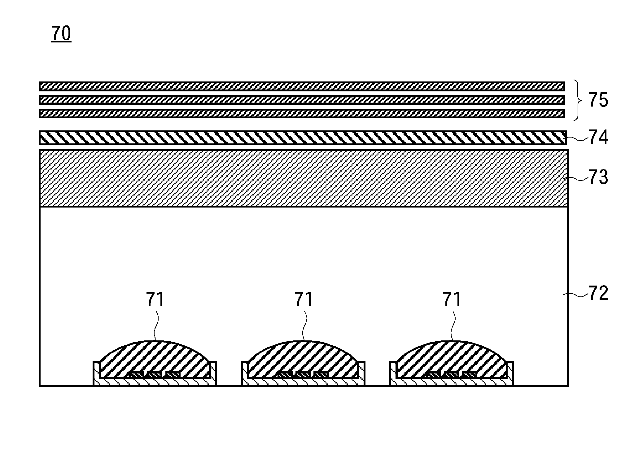
In order to suppress the chromaticity shift and corrosion associated with the deterioration of a sulfide phosphor particle, this phosphor sheet is produced using a phosphor particle-containing resin composition which comprises: covered phosphor particles; polymerizable compound; and a polymerization initiator. The covered phosphor particles are obtained by covering phosphor particles with silicon dioxide films, wherein among the phosphor particles, at least sulfide phosphor particles are covered with silicon dioxide films that contain a metal oxide powder. Thus, the phosphor sheet can be inhibited from emitting a sulfur-based gas, and exhibits a minimized chromaticity shift, even when the phosphor sheet is present in such a manner that the edge of the phosphor layer of the sheet is in an exposed state.

Description

CROSS-REFERENCE TO RELATED APPLICATIONS[0001]This application is a continuation of International Application No. PCT / JP2013 / 69289, filed on Jul. 16, 2013, which claims priority to Japan Patent Application No. 2012-165056, filed on Jul. 25, 2012. The contents of the prior applications are herein incorporated by references in their entireties.TECHNICAL FIELD[0002]The present invention generally relates to a phosphor sheet, including a phosphor layer formed of a phosphor-containing resin composition including a composition for film formation and a powdery phosphor particle that emits fluorescence when irradiated with excitation light.BACKGROUND ART[0003]Heretofore, a thin liquid crystal display uses a backlight that illuminates a liquid crystal panel from the back toward the front face of the liquid crystal panel, and is broadly classified into an edge lighting system and a direct lighting system depending on structures of the backlight.[0004]In the edge lighting system, incident light...

Claims


Application Information

Patent Timeline
IPC IPC(8): C09K11/77F21K99/00H01L25/075C09K11/02H01L33/50
CPCC09K11/7734C09K11/025C09K11/7733F21Y2101/02H01L33/505H01L25/0753F21K9/56H01L33/501C08F2/48H01L33/504C09K11/7731H01L2224/48091H01L2924/0002F21K9/64F21Y2115/10Y10T428/256G02F1/133614C09K11/77342H01L2924/00014H01L2924/00
Inventor TANI, HIROFUMIKUSUNOKI, TSUNEODAIMON, MASAHIDEITO, YASUSHIHORI, TOMOMITSU
Owner DEXERIALS CORP
Learn More